


Estimating RF Coverage
5-20
InterReach Fusion SingleStar Installation, Operation, and Reference Manual
CONFIDENTIAL
D-620605-0-20 Rev A
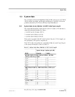
95% of the area being covered.
It is important to note that a design goal such as
–85 dBm is derived by taking into account multipath fading and log-normal shad-
owing characteristics. Thus, this design goal will only be met “on average” over
95% of the area being covered. At any given point, a fade may drop the signal
level beneath the design goal.
4.
Building information
:
• Two floor building with 9,290 sq. meters (100,000 sq. ft.) per floor; total
18,580 sq. meters (200,000 sq. ft.)
• Walls are sheetrock construction; suspended ceiling tiles
• Antennas used will be omni-directional, ceiling mounted
• Standard office environment, 50% hard wall offices and 50% cubicles
5.
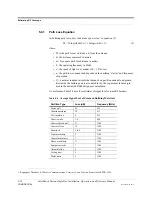
Path Loss Slope
: For a rough estimate, Table 5-11, “Estimated Path Loss Slope for
Different In-Building Environments” on page 5-16, shows that a building with 50%
hard wall offices and 50% cubicles, at 859 MHz, has an approximate path loss slope
(PLS) of 37.6. Given the RF link budget of 95.5 dB, the distance of coverage from
each RAU will be 52 meters (170.6 ft). This corresponds to a coverage area of
8,494 sq. meters (91,425 sq. ft.) per RAU (refer to Section 5.4.1 for details on path
loss estimation). For this case, assume a circular radiation pattern, though the actual
area covered will depend upon the pattern of the antenna and the obstructions in the
facility.
6.
Equipment Required
: Since you know the building size, you can now estimate
the Fusion SingleStar equipment quantities needed. Before any RF levels are
tested in the building, you can estimate that two antennas per level will be needed.
This assumes no propagation between floors. If there is propagation, you may not
need antennas on every floor.
a.
2 antennas per floor × 2 floors = 4 RAUs
b.
4 RAUs ÷ 8 (maximum 8 RAUs per Fusion SingleStar Hub) = 1 Hub
Check that the CATV cable distances are as recommended. If the distances differ,
use the tables in Section 5.3, “System Gain,” on page 5-11 to determine system
gains or losses. The path loss may need to be recalculated to assure adequate sig-
nal levels in the required coverage distance.
The above estimates assume that all cable length requirements are met. If RAUs can-
not be placed within reach of the Hub, then the InterReach Fusion SingleStar system,
with its longer reach, should be considered.
An RF Site Survey and Building Evaluation is required to accurately establish the
Fusion SingleStar equipment quantities required for the building. The site survey
measures the RF losses within the building to determine the actual PLS, which will be
used in the final path loss formula to determine the actual requirements of the Fusion
SingleStar system.
Содержание InterReach Fusion SingleStar
Страница 1: ...D 620605 0 20 Rev A Installation Operation and Reference Manual InterReach Fusion TM SingleStar ...
Страница 2: ...D 620605 0 20 Help Hot Line U S only 1 800 530 9960 Rev A CONFIDENTIAL ...
Страница 150: ...A 4 InterReach Fusion SS Installation Operation and Reference Manual CONFIDENTIAL D 620605 0 20 Rev A ...