Memory Module(s)
29
1
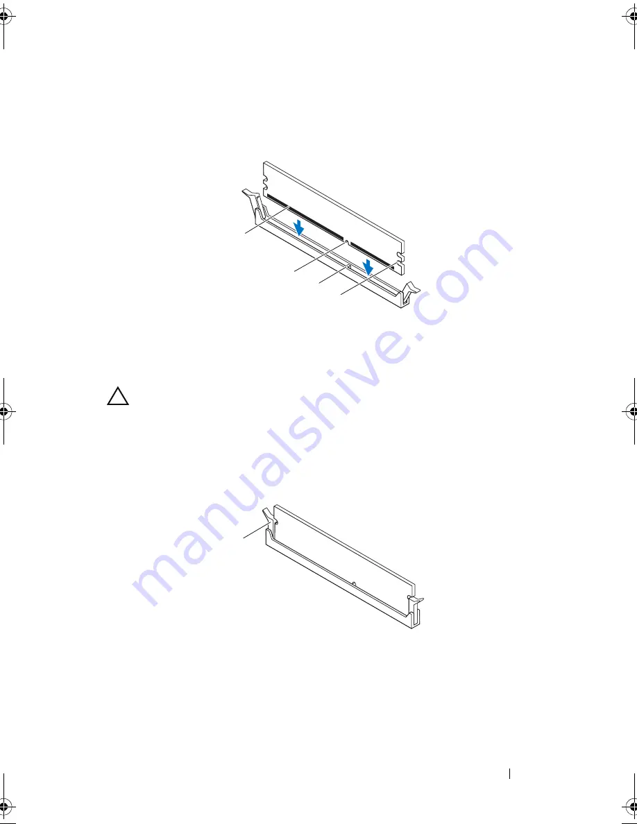
Align the notch on the bottom of the memory module with the tab on the
memory-module connector.
CAUTION:
To avoid damage to the memory module, press the memory module
straight down into the connector while you apply equal force to each end of the
memory module.
2
Insert the memory module into the memory-module connector until the
memory module snaps into position and the securing clip locks in place.
1 memory module
2 notch
3 tab
4 cutouts (2)
1 securing clip (snapped in position)
1
2
4
3
1
book.book Page 29 Wednesday, October 10, 2012 10:32 PM
Содержание XPS 8500
Страница 11: ...Contents 11 ...
Страница 12: ...12 Contents ...
Страница 16: ...16 After Working Inside Your Computer ...
Страница 18: ...18 Technical Overview Front View of Your Computer 1 2 3 11 10 9 8 7 6 1 5 4 ...
Страница 24: ...24 Computer Cover 1 thumbscrew 2 computer cover 2 1 ...
Страница 26: ...26 Computer Cover ...
Страница 42: ...42 Graphics Card ...
Страница 52: ...52 Wireless Mini Card ...
Страница 54: ...54 Mini Card Antennas 1 Mini Card antennas 2 2 screws 4 3 Mini Card antenna cables 4 top panel 2 3 4 1 ...
Страница 56: ...56 Mini Card Antennas ...
Страница 60: ...60 mSATA Drive ...
Страница 72: ...72 Optical Drive s ...
Страница 76: ...76 Media Card Reader ...
Страница 80: ...80 Top Cover ...
Страница 82: ...82 Top I O Panel 1 screws 2 2 top I O panel 3 top panel 2 1 3 ...
Страница 84: ...84 Top I O Panel ...
Страница 88: ...88 Front USB Panel ...
Страница 92: ...92 Power Button Module ...
Страница 96: ...96 Chassis Fan ...
Страница 100: ...100 Processor Fan and Heat Sink Assembly ...
Страница 110: ...110 Coin Cell Battery ...
Страница 114: ...114 Power Supply Unit ...
Страница 116: ...116 System Board 4 Lift the system board up and out of the chassis 1 screws 6 2 system board 1 2 ...
Страница 118: ...118 System Board ...
Страница 131: ...System Setup Utility 131 ...
Страница 132: ...132 System Setup Utility ...
Страница 136: ...136 Specifications ...


