- 28 -
Chiller Water-cooled Screw
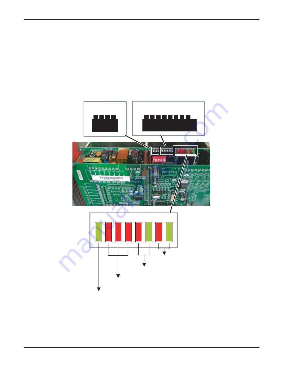
Fig. 12
1
2
3
4
D2 D3 D4
D5 D6 D7 D8 D9
Modbus Address: 0x01
1
2
3
4
5
6
7
8
OFF
OFF
OFF
OFF
ON
ON
ON
ON
ON
ON
ON
OFF
MODBUS
Communication
RS -232
Communication
4Hz Blink
PLC Normal:
OFF
DIP switch and indication LED is installed on the top of PLC. Normally D2 LED should be flicker-
ing as 4Hz frequency, D3~D6 should be OFF. Other LED is flickering depending on PLC commu-
nication condition.
4-position DIP switches should be OFF, 8-position DIP switch should indicates MODBUS slave
equipment address. 8-position DIP switch indicates 8 bit, number of 6 figures which has contrary
one bit as number of 2 figures. For example, basic setting place described in the picture below
(switch 2~8: ON and switch 1: OFF) indicates 0x7E and the contrary value is 0x01. Basic setting
of MODBUS slave address of chiller is 0x01.
Содержание RCWW-1
Страница 14: ... 14 Chiller Water cooled Screw User Setting Fig 5 ...
Страница 16: ... 16 Chiller Water cooled Screw Function Setting Fig 6 ...
Страница 18: ... 18 Chiller Water cooled Screw I O Display ...
Страница 23: ... 23 Operation Maintenance Manual Running Information Fig 8 ...
Страница 77: ......


