- 45 -
Operation & Maintenance Manual
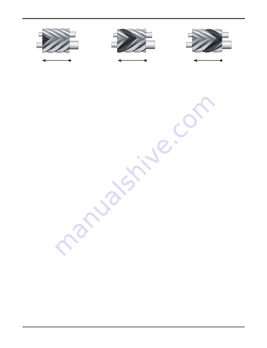
(C) Discharge
(B) Compression
(A) Suction and seal
Screw compressor has the 3~4 gear control or no gear capacity control (Step-less) system installed. Capacity
control system is composed of the slide valve, piston rod, cylinder, piston and piston ring. The slide valve and
the piston are connected through the piston rod. The operating principle is to push the piston to the cylinder by
using hydraulic pressure. Because the pressure of the oil is higher than the spring force, the oil that passed
through the oil filter will fill the cylinder through the capillary pipe through the sump. Differential pressure moves
the piston to the right side of the cylinder. When the slide valve moves to the right, the effective compression
volume inside the compression compartment increases. This increases the displacement of the refrigerant and
increases the cooling capacity. But, when the power is supplied to the solenoid valve, the oil in the piston cylin-
der moves to the suction port and the piston and slide valve moves to the left side, and part of the refrigerant
goes around from the compression compartment to the suction end again. In result, the cooling capability is
reduced due to the reduction of displacement of the refrigerant flowing inside the system.
Piston spring pushes the piston to its original place, that is minimum load location, to reduce the operating cur-
rent in the next start up. When the compressor starts form maximum load capacity, it can cause start up in over-
current situation. Capillary pipe is used for maintaining and limiting the appropriate amount of oil to flow into the
cylinder. Adjustment (Step-less) solenoid valve (SV1, SV2) is controlled by small controller or temperature
switch and can be adjusted to make the piston move smoothly for more stable cooling capacity.
If the oil filter cartridge, capillary pipe or adjustment solenoid valve do not operate inside the system, this can
cause malfunctioning or inefficiency operation of capacity control system.
To reduce the pressure inside the cylinder before the compressor stops, the unloading valve or solenoid valve
of the lowest step must be maintained for 20-30 seconds. For next start up, it must be located in unload position
for normal start up.
Fig. 18
Содержание RCWW-1
Страница 14: ... 14 Chiller Water cooled Screw User Setting Fig 5 ...
Страница 16: ... 16 Chiller Water cooled Screw Function Setting Fig 6 ...
Страница 18: ... 18 Chiller Water cooled Screw I O Display ...
Страница 23: ... 23 Operation Maintenance Manual Running Information Fig 8 ...
Страница 77: ......


