
6
INSTALLATION SCENE
E
N
G
L
IS
H
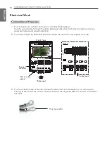
Signal
Pipe
Thermistor
4
11
6
8
9
7
2
10
5
1
Field supply
DDC
Air
flo
w
3
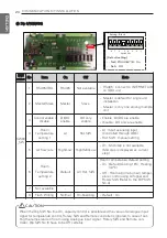
Parts and components
No.
Name
Remarks
1
AHU
Field supply
2
Outdoor Unit
Single CAC
3
AHU Communication Kit(PUDCA0)
-
4
DDC
Field supply(Central control Device)
5
Field piping
Field supply
Wiring connections
6
Communication Kit Wiring
Power supply and communication
between comm. kit and outdoor unit
7
Pipe thermistors
Evaporator (In/Out) control of AHU
8
Room thermistor
Return air control
9
Remote controller
(PQRCVSL0/ PQRCVSL0QW)
Optional accessory
10
PI485 (PMNFP14A0/PMNFP14A1)
Essential accessory
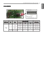
11
Signal
• Fan signal(Low / Middle / High)
• Defrost / Heating / Cooling signal
• Themal On/Off
CAUTION
• For installation of Room thermistor (No. 8), always place it at the inlet of Heat Exchanger.
Otherwise, it might not operate properly.
!
CAUTION
• Before installation of outdoor unit, check the serial Number, 1st digit indicates year, and 2nd/3rd
digits mean month of production. For example, 503KCSFONT26 was produced on March 2015.
!
INSTALLATION SCENE
* Applicable ODU model
Type
Model
Available
Standard
UU18W.UE4
All
UU24W.U44
UU30W.U44
UU70W.U34
Produced from May.2015
UU85W.U74