background image

6

PRDCAM 

AHU Communication Kit Installation Manual

Due to our policy of continuous product innovation, some specifications may change without notification. 


©LG Electronics U.S.A., Inc., Englewood Cliffs, NJ. All rights reserved. “LG” is a registered trademark of LG Corp.

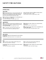
Do not install the communications and EEV kits in loca-

tions exposed to open flame or extreme heat. Do not touch 

the kits with wet hands.

There is risk of fire, electric shock, physical injury or death.

Do not modify or extend the power supply cords.

There is risk of fire, electric shock, physical injury or death.

Do not step or place anything on the communications 

and EEV kits.

If the product falls, there is risk of physical injury�

Do not place heavy objects on the communications and 

EEV kits’ power cables.

There is risk of fire, electric shock, physical injury or death.

Only authorized persons should operate the communications 

and EEV kits.

If the kits are not operated properly, there is a risk of physical injury�

Do not provide power to or operate communication and 

EEV kits if the kits are flooded or submerged. Always have 

the dealer or an authorized technician to service the kits.

There is risk of fire, electric shock, physical injury or death.

Do not store or use flammable gas or combustibles near 

the  communications and EEV kits.

There is risk of fire, explosion, and physical injury or death.

Unplug the communication and EEV kits if either kit emits 

strange sounds, smells, or smoke.

There is risk of fire, electric shock, physical injury or death.

Do not let the communication and EEV kits get wet.

There is risk of product failure or malfunction�

Only authorized persons should operate the communication 

and EEV kits.

There is risk of product failure or malfunction�

Do not drop the communications and EEV kits.

There is risk of product failure or malfunction�

Do not step or place anything on the communications 

and EEV kits.

If the product falls, there is risk of product damage�

OPERATION

DANGER

CAUTION

SAFETY PRECAUTIONS

Содержание PAHCMS000

Страница 1: ...INSTALLATION MANUAL FOR LG AIR HANDLER UNIT AHU COMMUNICATIONS KIT AHU Model Number PAHCMS000 ...

Страница 2: ...tals catalogs engineering installation owner s and service manuals visit www lghvac com Do not throw away destroy or lose this manual Please read carefully and store in a safe place for future reference Content familiarity required for proper installation The instructions included in this manual must be followed to prevent product malfunction property damage injury or death to the user or other pe...

Страница 3: ...Settings 10 AHU Communications Kit Parts 13 AHU Communications Kit Mounting 14 Power Wiring 18 Communications Wiring 19 Controller Settings 20 Solutions Overview 24 Main Module Settings 27 Communication Module 31 Defrost Setting 32 External Connection Diagrams 33 Discharge Air Temperature Controller 37 EEV Kit Installation 45 Introduction Specifications and Design Parameters 45 EEV Kit Parts 46 Mo...

Страница 4: ...an familiar with safety procedures and equipped with the proper tools and test instruments to install the kits Improper installation by the user may result in fire electric shock physi cal injury or death For replacement of an installed communications and EEV kits always contact a qualified LG service provider familiar with safety procedures and equipped with the proper tools and test instruments ...

Страница 5: ...e or the electric work is not performed properly it may result in fire electric shock physical injury or death Refer to local state and federal codes and use power wires of sufficient current capacity and rating Wires that are too small may generate heat and cause a fire and physi cal injury or death Secure all field wiring connections with appropriate wire strain relief Improperly securing wires ...

Страница 6: ...d EEV kits If the kits are not operated properly there is a risk of physical injury Do not provide power to or operate communication and EEV kits if the kits are flooded or submerged Always have the dealer or an authorized technician to service the kits There is risk of fire electric shock physical injury or death Do not store or use flammable gas or combustibles near the communications and EEV ki...

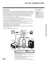
Страница 7: ...osed temperature sensor and controls the outdoor unit to secure the demanded supply air temperature It can be directly connected to direct digital control DDC without a separate control module so DDC can receive product control and status information through Modbus communication The PAHCMS000 AHU Communications Kit consists of a chassis communication module pipe in thermistor pipe out thermistor a...

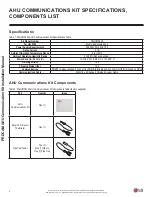
Страница 8: ...00 For Use With Multi V and Single Zone Power Supply Requirements 208 230VAC 60Hz 1Ph Rated Current 0 1A Ambient Operating Temperature Range 4 to 149 F Ambient Operating Humidity Range 0 to 98 Non condensing Dimensions in W x H x D 14 31 32 W x 6 3 32 H x 11 13 16 D Net Weight lbs 16 5 Shipping Weight lbs 19 4 Communications RS 485 4 wires required 2 connect to IDU A B terminals and 2 connect to U...

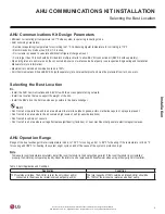
Страница 9: ...is 64 4 to 104 F for cooling and 41 to 86 F for heating If the temperature is 64 4 F for cooling and 86 F for heating the system might cycle on and off because of the system s protection logic Application Condition 100 outside air intake The AHU s is are the only indoor unit s connected to the air source water source heat pump unit s The total capacity of 100 outside air intake AHU s should be 50 ...

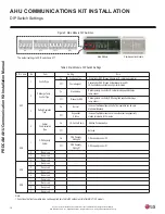
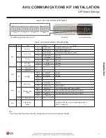
Страница 10: ...control by DDC using filed supplied discharge temp sensor 3 Defrost Operation Type On Normal In case of multiple outdoor units Defrost operation can be oper ated simultaneously Off Sequential Start up In case of multiple outdoor units the outdoor unit is sequentially started at intervals of 10 minutes 4 Central Communication Type On LG Central Comm Modbus Communication Off Not Used SW2 1 ODU Capac...

Страница 11: ...ntrolled by Modbus between modules Off Contact signal Not used 3 DO Type On Fan Speed Not used Off Status Not used 4 Fan Speed TH On Off On Fixed Not used Off Change Not used SW2 d e v r e s e R 1 d e v r e s e R 2 3 4 UI Setting Off Off UI Setting 1 Not used Off On UI Setting 2 Not used f f O n O n O n O SW3 1 Master Slave On Slave mode Not used Off Master mode Master is default 2 3 Operation mod...

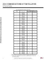
Страница 12: ... DIP Switch Settings for AHU Capacity SW4 DIP switches Capacity kBTU h MULTI V 5 2 1 1 7 5 1 2 9 8 1 3 2 1 4 2 4 5 1 8 2 5 8 1 6 3 6 4 2 2 4 7 0 3 8 4 8 6 3 4 5 9 2 4 6 7 0 1 8 4 6 9 1 1 0 6 5 1 1 2 1 0 7 4 3 1 3 1 5 8 3 5 1 4 1 d e v r e s e R 2 7 1 5 1 d e v r e s e R 2 9 1 6 1 Single Zone Switch Number Notes 1 PAHCMS000 AHU can be connected to the PRLK048A0 PRLK096A0 or PRLK396A0 EEV kits only ...

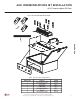
Страница 13: ...s a registered trademark of LG Corp 1 2 4 6 3 5 AHU COMMUNICATIONS KIT INSTALLATION AHU Communications Kit Parts Figure 5 AHU Communications Kit Parts Diagram Table 7 AHU Communications Kit Parts Table Diagram Label Part Name Quantity 1 Thermistor Assembly NTC Three 3 2 Harness Multi One 1 3 Main Module One 1 4 Communications Module One 1 5 Bracket One 1 6 Panel Assembly Control Three 3 ...

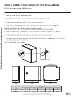
Страница 14: ...urface NOTE Do not drill holes without removing the control panel assembly Metal shavings can collect on the control panel assembly and damage the equipment when power is applied 5 Drill the four holes for the field supplied screws Ensure the drill bit does not damage any equipment or components 6 Carefully replace the control panel assembly and secure with the four nuts on the four captive bolts ...

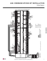
Страница 15: ...me specifications may change without notification LG Electronics U S A Inc Englewood Cliffs NJ All rights reserved LG is a registered trademark of LG Corp AHU COMMUNICATIONS KIT INSTALLATION Wiring Diagram Figure 7 AHU Communications Kit Wiring Diagram Thermistor Return ...

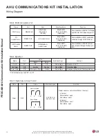
Страница 16: ...P e m a N Alarm DO1 30 VDC 5 A 250 VAC 5 A Output normal or error status Relay C Contact A Contact Normal status open Error status short B Contact Normal status short Error status open Normal Status A B COM Error Status A B COM n o i t c n u F c e p S l a c i r t c e l E m e t I t r o P e m a N ODU Comm RS485 CH2 ODU Comm CEN A B or INT A B Max 3280 ft 2C x 18 16 AWG shield wire Communication with...

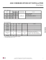
Страница 17: ...e D s u t a t s f f O n O n o i t a r e p o r o s s e r p m o C f f O n O 4 O D s u t a t S p m o C 5 O D d e v r e s e R 6 O D d e v r e s e R n o i t c n u F c e p S l a c i r t c e l E e u l a V t r o P e m a N 1 I U d e v r e s e R 2 I U d e v r e s e R 3 I U d e v r e s e R 4 I U d e v r e s e R 5 I U d e v r e s e R 6 I U d e v r e s e R Capacity Control 0 10V UI7 AI 0 10 V Input DC 0 10 V 2...

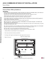
Страница 18: ... poles must be incorporated in the wiring Improper installation by the user may result in fire electric shock physical injury or death Refer to the air source water source heat pump unit installation manual for power wiring sizes circuit breaker and switch capacities and wiring instructions If the power source capacity for the air source unit water source unit is inadequate or the electric work is...

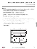
Страница 19: ...l Code and the instructions in this manual If the electrical work is not performed properly it may result in fire electric shock physical injury or death All field supplied parts materials and electric work must be conform to local codes Improper components and installation may result in fire electric shock physical injury or death Ensure the power source is disconnected before performing this pro...

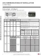
Страница 20: ... to heating only mode UI2 Open status will work as fan mode Forced Thermo On Off UI3 DI Thermal On Thermal Off Non voltage When UI4 Target temp is less than 1 5 V Target temp and Room temp is fixed like below table Target Temp UI4 AI Voltage Electrical Spec Cooling Mode F V Min Max 1 5 0 1 6 DC 0 10 V 20 mA UI3 short 60 UI3 open 80 UI3 short 80 UI3 open 60 0 6 0 6 1 2 9 1 0 2 2 6 2 6 6 2 4 2 5 2 4...

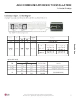
Страница 21: ...rol Forced Th On Off UI4 DI Thermal On Thermal Off Non voltage Mode Status n o i t c n u F c e p S l a c i r t c e l E UI2 UI3 Cooling Short Open Non voltage Cooling mode operation control Heating Open Short Non voltage Heating mode operation control Fan Open Open Non voltage Fan mode operation control Short Short Non voltage Mode Thermal On Target temp 60 Room temp 80 Target temp 80 Room temp 60 ...

Страница 22: ...s e d o m t s o r f e d l a t o t y l n O s u t a t S t s o r f e D U D O l a m r o N t s o r f e D 2 O D t s o r f e D s u t a t s t u p t u o r o r r E l a m r o N r o r r E 3 O D m r a l A Value n o i t c n u F c e p S l a c i r t c e l E Short Open Fan_High DO1 High 12 VDC 1A 250VAC 3A Fan High d i M _ n a F d i M 2 O D d i M _ n a F w o L _ n a F w o L 3 O D w o L _ n a F Fan_Stop DO1 DO2 DO3...

Страница 23: ...th Wired Remote Controller n o i t c n u F c e p S l a c i r t c e l E m e t I t r o P e m a N EEV 12 VDC 1 2 3 4 EEV Control Max 32 8 ft EEV Control n o i t c n u F t r o P e m a N x T m m o C s u b d o M 1 D E L L 1 0 D L x R m m o C s u b d o M 2 D E L L 2 0 D L x T m m o C r e n n I 3 D E L L 3 0 D L x R m m o C r e n n I 4 D E L L 4 0 D L U D O h t i w g n i t a c i n u m m o c n e h w f f O ...

Страница 24: ...mperature Te by monitoring the supplied air temperature Td to meet the required set target Td Required item Function List Note O Applied X Not applied 1 LG Central controller is based on AC Smart IV and ACP IV Function List LG Remote Controller LG Central Controller 1 Control Operating On Off O O Operation Mode O O Return Air Temperature X X Discharge Air Temperature O O Forced Thermal On Off X X ...

Страница 25: ...s Kit adjusts the outdoor unit target temperatures Te increasing or decreasing the discharge air temperatures Required Items Function List Note O Applied X Not applied 1 LG central controller is based on AC Smart IV and ACP IV Function List Contact Signal type DDC LG Remote Controller LGCentralController1 Control Operating On Off O X X Operation Mode O X X Return Air Temperature X X X Discharge Ai...

Страница 26: ...tions Kit The AHU Communications Kit adjusts the outdoor unit target temperatures Te increasing or decreasing the discharge air temperatures Required Items Function List Note O Applied X Not applied 1 LG Central controller is based on AC Smart IV and ACP IV Function List Modbus Comm type DDC LG Remote Controller LGCentralController1 Control Operating On Off O O O Operation Mode O O O Return Air Te...

Страница 27: ... an AHU heat exchanger Voltage V Total Capacity ratio Each ODU s capacity ratio ODUMaster 1 ODUMaster 2 2 0 0 Operation Off 2 0 20 0 40 0 2 5 25 0 50 0 3 0 30 0 60 0 3 5 35 0 70 0 4 0 40 0 40 40 4 5 45 0 40 50 5 0 50 0 50 50 5 5 55 0 50 60 6 0 60 0 60 60 6 5 65 0 60 70 7 0 70 0 70 70 7 5 75 0 70 80 8 0 80 0 80 80 8 5 85 0 80 90 9 0 90 0 90 90 9 5 95 0 90 100 10 0 100 0 100 100 Voltage V ODU Capaci...

Страница 28: ... sale person to design AHU heat exchanger Voltage V Total Capacity ratio Each ODU s capacity ratio ODU Master 1 ODU Master 2 ODU Master 3 ODU Master 4 2 0 0 0 Operation Off 2 0 20 0 40 0 40 0 2 5 22 5 50 0 40 0 3 0 25 0 60 0 40 0 3 5 27 5 70 0 40 0 4 0 40 0 40 40 40 40 4 5 47 5 40 50 50 50 5 0 50 0 50 50 50 50 5 5 57 5 50 60 60 60 6 0 60 0 60 60 60 60 6 5 67 5 60 70 70 70 7 0 70 0 70 70 70 70 7 5 ...

Страница 29: ...e table above are not exact 2 Evaporative temperature Condenser temperature may vary depending on system operating frequency pressure option setting and piping installationconditions Voltage V ODU Capacity ratio Eva Temp Te Cond Temp Tc V Min Max 1 0 0 7 Operation Off 1 0 0 8 1 2 100 39 2 122 0 2 0 1 8 2 2 90 41 0 120 2 3 0 2 8 3 2 80 43 7 116 6 4 0 3 8 4 2 70 46 4 111 2 5 0 4 8 5 2 60 50 0 104 0 ...

Страница 30: ...ded when PAHCMS000 is connected to an LG central controller The address of main module can be set within 1 247 In this case the address of the main module should be the same as the address in LG central controller Setting Method Press Set button red Select Addr in 7 Segment using buttons and then press the Set button Press ESC button to exit Communication Module Main Module Name Port Function L01L...

Страница 31: ...ol Name Port Item Electrical Spec Function REMO 12V SIG GND Wire Remote Controller Max 164 ft Communication with Wired Remote Controller Name Port Item Electrical Spec Function Thermistor Discharge NTC RI2 G Discharge air Thermistor NTC10kΩ 16 4ft Discharge Air temperature sensor ThermistorPipein NTC RI3 G Pipe in Liquid Thermistor NTC5kΩ 16 4ft Inlet pipe Liquid Temp sensor Thermistor Pipe out NT...

Страница 32: ...n is only applied to the MULTI V outdoor unit after MULTI V 5 Operating condition Power on Heating operation command Stop condition Power off or stop command Function operation 1 This function is available when DIP switch is set to the Sequential Start Up 2 In order to prevent the outdoor unit from entering the defrosting at the same time of heating operation only half of the outdoor unit is in op...

Страница 33: ... Liquid Thermistor DX Coil Fuse R S TN Power Supply DischargeThermistor 1 Central Controller ACP CH5 AC SMART CH1 A B Power Supply L N Main module Comm module ODU Capacity Control 0 10V A B CH3 A B CH2 RI2 G RI3 G RI4 G Local AHU Controller Field Supplied CH 2 A On Off Cool Heat Emer stop CH 2 B Adapter On Off Defrost Alarm Comp status 12V L N EEV SIG GND Remote Controller Refrigerant Piping Field...

Страница 34: ... Liquid Thermistor DX Coil L N Power Supply Discharge Thermistor Central Controller ACP CH5 AC SMART CH1 A B Main module Comm module ODU Capacity Control 0 10V A B A B CH3 CH2 RI2 G RI3 G SINGLE N RI4 G Local AHU Controller Field Supplied On Off Cool Heat Emer stop SINGLE S Adapter On Off Defrost Alarm Comp status 12V SIG GND L N RefrigerantPiping FieldSupply Wire Thermistor LGSupply Wire FieldSup...

Страница 35: ...ischarge Thermisto r Power Supply 1 Central Controller ACP CH5 AC SMART CH1 A B Power Supply L N Main module Comm module A B CH3 A B CH2 RI2 G RI3 G RI4 G Modbus Communication Local AHU Controller Field Supplied CH 2 A A CH4 B CH4 CH 2 B 12V Adapter L N EEV SIG GND Remote Controller RefrigerantPiping FieldSupply Wire Thermistor LGSupply Wire FieldSupply AI DI DO Signal Field Supply Note 1 The type...

Страница 36: ...out Gas Thermistor AirHandlingUnit field supply Pipe in Liquid Thermistor DX Coil L N Power Supply Discharge Thermistor Central Controller ACP CH5 AC SMART CH1 A B Main module Comm module A B CH3 A B CH2 RI2 G RI3 G SINGLE N SINGLE S RI4 G Modbus Communication Local AHU Controller Field Supplied A CH4 B CH4 Adapter 12V SIG GND L N EEV Remote Controller RefrigerantPiping FieldSupply Wire Thermistor...

Страница 37: ... 00 RA temp controller Master 02 01 RA temp controller Master 02 02 RA temp controller Master 02 03 Outdoor Unit 00 Main Module 001 Modbus communication line Power line Remote Controller1 L N Discharge air temp controller Note 1 RemotecontrollershouldbeconnectedtoPAHCMS000 2 LGCentralcontrolleraddressingfordischargeairtemp controllershouldbeset to thesameaddressas themainmodule s address 3 Address...

Страница 38: ...ipe in out sensor RA temp controller Master 02 01 Pipe in out sensor RA temp controller Master 02 02 ODU com Pipe in out sensor RA temp controller Master 02 03 Power line Discharge air temp controller L N Note 1 RemotecontrollershouldbeconnectedtoPAHCMS000 2 LGCentralcontrolleraddressingfordischargeairtemp controllershouldbeset to thesameaddressas themainmodule s address 3 Address of Comm module o...

Страница 39: ...nication Remote Controller1 line Discharge air sensor Pipe in out sensor L N Pipe in out sensor Pipe in out sensor Pipe in out sensor Communication module Master 02 00 RA temp controller Master 02 01 RA temp controller Master 02 02 RA temp controller Master 02 03 Outdoor Unit 00 Main module 002 ODU communication line Remote Controller1 L N Discharge air temp controller Note 1 Remotecontrollershoul...

Страница 40: ...odule Master 02 00 RA temp controller Master 02 01 RA temp controller Master 02 02 RA temp controller Master 02 03 Outdoor Unit 00 Main module 001 Modbus Power line Contact signal L N Remote Controller1 Discharge air temp controller Note 1 RemotecontrollershouldbeconnectedtoPAHCMS000 2 LGCentralcontrolleraddressingfordischargeairtemp controllershouldbeset to thesameaddressas themainmodule s addres...

Страница 41: ...ster 02 00 RA temp controller Master 02 01 RA temp controller Master 02 02 RA temp controller Master 02 03 Outdoor Unit 00 Main module 001 Modbus Power line Contact signal L N Remote Controller1 Discharge air temp controller Note 1 RemotecontrollershouldbeconnectedtoPAHCMS000 2 LGCentralcontrolleraddressingfordischargeairtemp controllershouldbeset to thesameaddressas themainmodule s address 3 Addr...

Страница 42: ...t 00 Power line Modbus communication Remote Controller1 line Discharge air sensor Pipe in out sensor L N Pipe in out sensor Pipe in out sensor Pipe in out sensor RA temp controller Master 02 03 Communication module Master 02 00 RA temp controller Master 02 01 RA temp controller Master 02 02 Outdoor Unit 00 Main module 002 ODU communication line Remote Controller1 Discharge air temp controller L N ...

Страница 43: ...proper AHU Communications Kit operation 1 Return Air Room Thermistor Install it at the AHU heat exchanger inlet in the return air stream 2 Pipe In Thermistor Install it behind the distributor on the coldest area in the heat exchanger contact the heat exchanger manufacturer for the precise location 3 Pipe Out Thermistor Install it at the outlet of the heat exchanger as close as possible to the heat...

Страница 44: ... cable to avoid strain on the thermistor cable and loosening of the thermistor Strain on the thermistor cable or loosening of the thermistor can result in bad contact with the pipe and incorrect temperature measurement Attaching the Pipe Thermistors To avoid water accumulating on the thermistor tip position the thermistor cable slightly below the thermistor tip or install the thermistor tip parall...

Страница 45: ...HU The EEV Kits for PAHCMS000 are offered in four sizes PRLK048A0 supports 12 through 96 MBH 8 tons maximum PRLK096A0 supports 96 1 through 192 MBH 16 tons maximum PRLK396A0 supports 192 1 MBH through 396 MBH 32 ton maximum PRLK594A0 supports 396 1 MBH through 594 MBH coils 48 ton maximum requires EEV Controller Module PAEEVA020 Model Number PRLK048A0 PRLK096A0 PRLK396A0 PRLK594A0 For Use With PAH...

Страница 46: ...iagram Label Part Name Quantity 1 Top Panel One 1 2 Bracket Two 2 3 Terminal Box One 1 4 Cable Connectors Two 2 5 Pipe Insulation One 1 6 Electronic Expansion Valve Assembly EEV Strainer Tube One 1 7 Support Tie One 1 8 Bottom Panel One 1 Table 15 PRLK048A0 and PRLK096A0 EEV Parts Table Figure 17 PRLK048A0 and PRLK096A0 EEV Parts 1 2 3 4 Table 16 PRLK396A0 EEV Parts Table Diagram Label Part Name Q...

Страница 47: ... Electronics U S A Inc Englewood Cliffs NJ All rights reserved LG is a registered trademark of LG Corp EEV KIT INSTALLATION EEV Kit Parts Table 17 PRLK594A0 EEV Parts Table Figure 19 PRLK594A0 EEV Parts Diagram Label Part Name Quantity 1 Panel A Upper One 1 2 Panel B Upper One 1 3 Bracket Two 2 4 Panel Base One 1 1 2 3 4 ...

Страница 48: ...on on the wall or ceiling where the holes for the screws should be placed Drill the four 4 holes 3 Attach the EEV Bottom Panel securely using four 4 field supplied 1 4 inch long screws Figure 20 Removing the Screws Figure 21 EEV Bottom Panel Hole Dimensions Mounting the EEV Kit Mounting the PRLK396A0 PRLK594A0 EEV Kit 1 Remove the two screws from the EEV kit base plate 3 Remove the four screws fro...

Страница 49: ... the connector pipe not provided at the outdoor unit 4 When connecting the outdoor unit s connector pipe and the EEV KIT pipe be sure to use a socket not provided that meets the necessary specifications 5 As the size of the EEV KIT pipe and the outdoor unit s connector pipe could vary check the sizes beforehand and use a socket that meets the necessary specifications 6 When brazing make sure to fo...

Страница 50: ...em operation When brazing the field piping to the EEV Kit Assembly use a wet cloth to pro tect and ensure that the main EEV body temperature does not exceed 248 F Make sure that the other parts such as electrical box support ties and wiring are also protected from direct flames during brazing After brazing is complete use medical grade dry nitrogen and pressure test the refrigerant piping system t...

Страница 51: ...rewing the four 4 M4 screws 2 Run field supplied wiring six 6 wired 18AWG stranded shielded copper to from the AHU Communications Kit through the cable connector on the EEV Kit 3 Connect wiring to the terminal connections as shown C following the label and color codes pasted onto the bottom of the terminal box and listed on the AHU Communications Kit PCB diagram Securely tighten all connections 4 ...

Страница 52: ...the four 4 screws 6 Taking care not to damage the field supplied wiring or insulation reattach the EEV Kit Top Panel by securing it with the screws at the four 4 corners BR Brown RD Red BL Blue OR Orange YL Yellow WH White Field Wiring A B PRLK396A0 EEV Kit cover removed 10 3 4 7 1 2 Mounting Hole 1 4 Pipe Outlet 5 8 to AHU coil liquid pipe connection Pipe Inlet 5 8 from ODU D D AHU controller Det...

Страница 53: ...artial lock is available only with Premium remote controller 5 Refer to the product manual of the remote controller Function List PAHCMS000 Basic Function Operating On Off O Operation Mode Control Cooling Heating only Desired Return Air Temperature Setting X Return Air Temperature Display X Desired Discharge Air Temperature Setting 60 80 F Discharge Air Temperature Display 51 8 103 1 F Fan Speed C...

Страница 54: ...Air Temperature Display 58 0 212 0 F Fan Speed Control X Auto Swing All Lock X Additionalfunction Schedule O Partial Lock X Auto Change Over X Set Back X 2 Set Auto Mode X Pipe Temperature X Error Code Display O Defrost Status X Outdoor unit Cycle Monitoring X Filter Sign Emergency Stop O Energy Navigation X Auto Control Peak Control Priority control X ODU capacity control X Time limit control X D...

Страница 55: ...eserved 10011 ODU 1 Operation Status 0 Off 1 On 10012 ODU 1 Comp Status 0 Off 1 On 10013 ODU 1 Defrost Status 0 Normal 1 Defrost 10014 ODU 1 Error Status 0 Normal 1 Error 10015 ODU 2 Operation Status 0 Off 1 On 10016 ODU 2 Comp Status 0 Off 1 On 10017 ODU 2 Defrost Status 0 Normal 1 Defrost 10018 ODU 2 Error Status 0 Normal 1 Error 10019 ODU 3 Operation Status 0 Off 1 On 10020 ODU 3 Comp Status 0 ...

Страница 56: ...er Register Description Value explanation 1 2 3 4 5 6 10027 Reserved 10028 Reserved 10029 Reserved 10030 Reserved 30001 Error Code 1xxxx 2 30002 Reserved 30003 Reserved 30004 Reserved 30005 Reserved 30006 Reserved 30007 Reserved 30008 Reserved 30009 Reserved 30010 Reserved 30011 RA Temp x10 30012 Reserved 30013 SA Temp x10 30014 Reserved 30015 Reserved 30016 Reserved 40001 Operation Mode 0 Cooling...

Страница 57: ...procedure 1 Connect the power and turn the system on 2 Check remote controller for error codes For more detailed function of the wired remote controller refer to its Owner s Installation Manual Buttons 3 4 11 12 on the wired remote controller do not operate TESTING Figure 28 Wired Remote Controller Buttons 1 7 8 9 10 11 13 12 14 15 16 17 2 3 4 5 6 1 Operation indication screen 2 Set temperature bu...

Страница 58: ...Thermistor Error Pipe out thermistor has disconnected from AHU or has short circuited Problem Cause Solution AHU Communications Kit Does Not Work No Power Check the power supply electrical connections and voltage Wiring is Incorrect Check the AHU Communications Kit electrical connections see wiring diagram AHU Communications Kit is Damaged Check AHU Communications Kit electrical and mechanical com...

Страница 59: ...Contact your LG representative if you have any questions about the AHU Communications Kit or its installation ...

Страница 60: ...Air Conditioning Division 4300 North Point Parkway Alpharetta Georgia 30022 www lg vrf com IM_AHU_Comm_Kit_PAHCMS000_8_18 LG Customer Information Center Commercial Products 1 888 865 3026 USA Follow the prompts for commercial A C products ...

Отзывы: