42
PRDCAM
AHU Communication Kit Installation Manual
Due to our policy of continuous product innovation, some specifications may change without notification.
©LG Electronics U.S.A., Inc., Englewood Cliffs, NJ. All rights reserved. “LG” is a registered trademark of LG Corp.
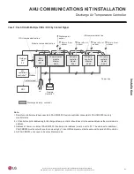
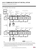
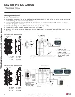
AHU COMMUNICATIONS KIT INSTALLATION
Discharge Air Temperature Controller
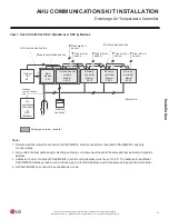
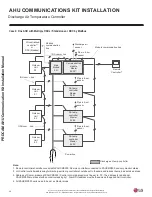
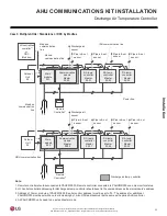
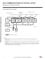
Case 1: Multiple AHUs / DDC by Contact Signal
Contact Signal
IDU communication line
Discharge air
sensor
Pipe in & out
sensor
Modbus
communication line
Module
communication line
Pipe in & out
sensor
Pipe in & out
sensor
Pipe in & out
sensor
RA temp.
controller
<Master>
02:03
Communication
module
<Master>
02:00
RA temp.
controller
<Master>
02:01
RA temp.
controller
<Master>
02:02
Main
module
001
Outdoor
Unit
00
Power line
Modbus
communication
Remote
Controller
1)
line
Discharge air
sensor
Pipe in & out
sensor
L N
Pipe in & out
sensor
Pipe in & out
sensor
Pipe in & out
sensor
RA temp.
controller
<Master>
02:03
Communication
module
<Master>
02:00
RA temp.
controller
<Master>
02:01
RA temp.
controller
<Master>
02:02
Outdoor
Unit
00
Main
module
002
ODU communication line
Remote
Controller
1)
Discharge air temp. controller
L N
Note:
1. RemotecontrollershouldbeconnectedtoPAHCMS000. Remote controller connected to PAHCMR000 can only monitor status.
2. LGCentral controlleraddressing fordischargeairtemp.controllershould beset to thesameaddress asthemainmodule’s address.
3. Address of Comm. module of PAHCMS000 (Central control address) must be set to ‘00’. The address for additional
PAHCMR000 mustbe set with an orderincreasing by1. Also ODU address must be the same as the paired AHUcontroller.
4. All PAHCMR000 units need to be set as Master mode.
LG
centralized
controller
2)
DDC

