51
Installation
Due to our policy of continuous product innovation, some specifications may change without notification.
©LG Electronics U.S.A., Inc., Englewood Cliffs, NJ. All rights reserved. “LG” is a registered trademark of LG Corp.
EEV KIT INSTALLATION
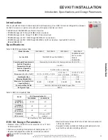
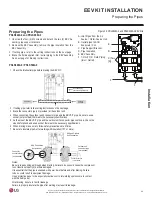
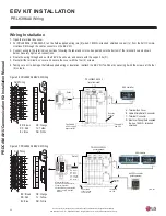
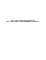
A. Terminal Box Cover
B. Cable Connector
C. Terminal Connections
D. Support Tie
E. Field-Supplied Wiring (Six [6] Wires, 18 AWG,
Stranded, Shielded)
A
B
D
E
B
R
R
D
B
L
O
R
Y
L
W
H
EEV
C
Detailed View
E
BR: Brown
RD: Red
BL: Blue
OR: Orange
YL: Yellow
WH: White
13-5/16"
7-1/2"
Mounting
Hole 1/4"
To AHU
Communications
Kit
EEV Kit
(Top Cover Removed)
Pipe Outlet 1/2"
to AHU coil liquid
pipe connection
Pipe
Inlet 1/2"
from ODU
F: Terminal Connection Label
F
Figure 25: PRLK048A0 and PRLK096A0 EEV Kit Wiring.
Wiring Installation
1. Open the terminal box cover (A) by unscrewing the four (4) M4 screws.
2. Run field-supplied wiring (six [6] wired, 18AWG, stranded, shielded copper) to / from the AHU Communications Kit through the cable
connector on the EEV Kit.
3. Connect wiring to the terminal connections as shown (C), following the label and color codes pasted onto the bottom of the terminal box
and listed on the AHU Communications Kit PCB diagram. Securely tighten all connections.
4. Route the wiring through and out the EEV Kit as shown, and secure with the support tie (D).
5. Re-install the terminal box cover (A) and secure with the four (4) M4 screws.
6. Taking care not to damage the field-supplied wiring or insulation, reattach EEV Kit top panel by securing with screws at four (4) corners.
Before connecting the field-supplied wiring, compare with the connection labels between EEV Kit and AHU Communications Kit. Connect the
wiring according to the PCB diagram for the AHU Communications Kit� If the wiring is incorrect, the products will malfunction�
PRLK048A0 and PRLK096A0 Wiring

