44
PRDCAM
AHU Communication Kit Installation Manual
Due to our policy of continuous product innovation, some specifications may change without notification.
©LG Electronics U.S.A., Inc., Englewood Cliffs, NJ. All rights reserved. “LG” is a registered trademark of LG Corp.
Water
Thermistor Installation
AHU COMMUNICATIONS KIT INSTALLATION
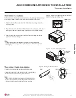
Figure 13: Steps to Attaching the Pipe Thermistors.
45°
Most Sensitive
Area on the
Thermistor
Maximize Contact Area
Figure 14: Thermistor Tip Contact Area.
Figure 15: Positioning the Thermistor Cable and Tip.
Tips for Attaching the Pipe In / Pipe Out Thermistors
• Put the thermistor cable in a separate protective tube.
• Always add a pull-relief to the thermistor cable to avoid strain on
the thermistor cable and loosening of the thermistor. Strain on the
thermistor cable or loosening of the thermistor can result in bad
contact with the pipe and incorrect temperature measurement.
Attaching the Pipe Thermistors
• To avoid water accumulating on the thermistor tip, position
the thermistor cable slightly below the thermistor tip, or
install the thermistor tip parallel with the cable.
Do not include a 90° angle or a kink in the thermistor
cable, nor install the thermistor tip upside down.
1. Securely attach the thermistor to the pipe with a field-supplied
pipe strap.
2. Insulate the thermistor with a field-supplied insulation sheet that
is >5t.
Thermistors must be securely attached with a pipe strap� The equip-
ment will not operate properly if thermistors are not making good
physical contact in the appropriate installation location�
Step 1
Step 2

