background image

INTRODUCTION   |   35

General Refrigerant Piping System Information

Due to our policy of continuous product innovation, some specifications may change without notification.


© 

LG Electronics U.S.A., Inc., Englewood Cliffs, NJ. All rights reserved. “LG” is a registered trademark of LG Corp.

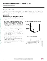
Flaring Procedure

Flaring and Brazing Procedures

One of the main causes of refrigerant leaks is a defective connection. The installer needs to know how perform both flared and brazed con-

nections successfully.

When selecting flare fittings, always use a 45° fitting rated for use with high pressure refrigerant R410A. Selected fittings must also comply with local, 

state, or federal standards.

• During installation, it is imperative to keep the piping system free of contaminants and debris such as copper burrs, slag, or carbon dust.

• 

Do not use kinked pipe caused by excessive bending in one specific area on its length.

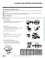
3. Flaring the pipe end.

• Use the proper size flaring tool to finish flared connections as 

shown.

• ALWAYS create a 45° flare when working with R410A.

1. Cut the pipe to length.

• Measure the distance between the indoor unit and the outdoor unit.
• Cut the pipes a little longer than measured distance.

2A. Remove the burrs.

• Completely remove all burrs from pipe ends.
• When removing burrs, point the end of the copper pipe down to 

avoid introducing foreign materials in the pipe.

2B. Slide the flare nut onto the copper tube.

90°

Slanted   Uneven  Rough

Pipe

Reamer

Point

down

Flare nut

Copper

tube

Bar

Copper pipe

Clamp handle

Red arrow

Cone

Bar

Slanted

Smooth

Uneven

Thickness

1.

2A.

2B.

3.

4.

4. Carefully inspect the flared pipe end.

• Compare the geometry with the figure to the right  

• If the flare is defective, cut it off and re-do procedure.
• If flare looks good, blow the pipe clean with dry nitrogen.

90°

45°

“A”

R=0.4 

– 0.8

Dimensions of the Flare.

Pipe Size (in. O.D.)

“A” Dimension (mm [in.])

1/2 

1/4

5/8

3/8

3/4

Flared Connection Dimensions / Tightening Torque.

Handle

Incorrect Flare

Even Length

Cracked

Yoke

Inside is shiny with no scratches

Surface

Damaged

Copper

tube

Outside Diameter (mm)

6.35

9.52

12.7

15.88

19.05

~

 9.1 (11/32 - 23/64)

~

 13.2 (1/2 - 33/64)

~

 16.6 (41/64 - 21/32)

~

 19.7 (49/64 - 25/32)

-

FLARING AND BRAZING PROCEDURES

Содержание LV181HV4

Страница 1: ...TICAL AIR HANDLING UNIT INSTALLATION MANUAL Single Zone Vertical Air Handling Unit System 18 000 48 000 Btu h LV420HV 42 000 Btu h LV480HV 48 000 Btu h LV181HV4 18 000 Btu h LV241HV4 24 000 Btu h LV361HV4 36 000 Btu h ...

Страница 2: ...of safety precautions begins on page 3 For more technical materials such as submittals engineering databooks and catalogs visit www lghvac com For continual product development LG Electronics U S A Inc reserves the right to change specifications without notice LG Electronics U S A Inc This document as well as all reports illustrations data information and other materials are the property of LG Ele...

Страница 3: ...ay enter the unit causing fire electric shock and physical injury or death Always check for system refrigerant leaks after the unit has been installed or serviced Exposure to high concentration levels of refrigerant gas may lead to illness or death Wear protective gloves and safety goggles when handling equipment Sharp edges may cause personal injury Dispose the packing materials safely Packing ma...

Страница 4: ...priate actions at the end of HVAC equipment life to recover recycle reclaim or destroy R410A refrigerant according to applicable U S Environmental Protection Agency EPA rules Periodically check that the outdoor frame is not damaged There is a risk of equipment damage Install the unit in a safe location where nobody can step on or fall onto it Do not install the unit on a defective stand There is r...

Страница 5: ...an industry qualified experienced certified electrician familiar with the U S National Electric Code NEC who is equipped with the proper tools and test instruments Failure to carefully read and follow all instructions in this manual can result in equipment malfunction property damage personal injury or death All electric work must be performed by a licensed electrician and conform to local buildin...

Страница 6: ...If gas leaks out ventilate the area before operating the unit If the unit is mounted in an enclosed low lying or poorly ventilated area and the system develops a refrigerant leak it may cause fire electric shock explosion physical injury or death To avoid physical injury use caution when cleaning or servicing the air conditioner Do not allow water dirt or animals to enter the unit There is risk of...

Страница 7: ...on 38 Outdoor Unit Connections 39 Indoor Unit Connections 40 Drain Hose 41 Bundling and Cutting Line 42 Electrical System Installation 45 General Information and Safety Guidelines 45 Power Wiring Specifications and Best Practices 46 Wall Controller Installation 49 External Static Pressure Setting Values 50 Indoor Unit Electrical Connections 51 Outdoor Unit Electrical Connections 52 ndoor Unit Wiri...

Страница 8: ...1 H System Type Style SV High Efficiency Inverter VP Gallery YV Premier EV Mega V Standard Inverter T Thermostat Compatible Nominal Capacity Nominal cooling capacity in Btu h Frame Type A Art Cool S Standard C Four Way Ceiling Cassette D Ceiling Concealed Duct Low Static H Ceiling Concealed Duct High Static V Vertical Horizontal Air Handling L LG 18 18 000 24 24 000 36 36 000 42 42 000 48 48 000 L...

Страница 9: ...nd Baffle Cooling F DB Yes 4 Heating F WB 4 to 64 Indoor Unit Operating Range Cooling F WB 57 to 77 Heating F DB 59 to 81 Indoor Temperature Setting Range Cooling F DB 65 to 86 Heating F WB 61 to 86 EEV Electronic Expansion Valve IDU Indoor Unit ODU Outdoor Unit This unit comes with a dry helium charge This data is rated 0 ft above sea level with 24 6 ft of refrigerant line per indoor unit and a 0...

Страница 10: ...actory Set High External Static Pressure in wg Constant CFM 0 1 1 0 ESP 0 3 0 3 Piping Liquid in 3 8 Vapor in 5 8 Indoor Unit Condensate Drain O D I D in Primary Secondary 3 4 FPT Minimum Maximum Pipe Length ft 5 6 6 164 6 6 164 6 6 246 6 6 246 6 6 246 Piping Length no additional refrigerant ft 24 6 Maximum Elevation Difference ft 98 4 EEV Electronic Expansion Valve IDU Indoor Unit ODU Outdoor Uni...

Страница 11: ...ion MOP is calculated as follows Largest motor FLA x 2 25 Sum of other motor FLA rounded down to the nearest standard fuse size Table 3 Vertical Air Handling Unit ODU Electrical Data Electrical Data Nominal Tons Model Name Unit Power Supply Compressor Quantity Compres sor Motor RLA Cooling Condenser Fan Motor s Hz Volts Voltage Range MCA MOP Condenser Fan Quan tity Condenser Fan Motor FLA 1 5 LUU1...

Страница 12: ...llow the placement guidelines set forth in Clearance Requirements Don t Where it will be subjected to direct thermal radiation from other heat sources or an area that would expose the outdoor unit to heat or steam like discharge from boiler stacks chimneys steam relief ports other air conditioning units kitchen vents plumbing vents and other sources of extreme temperatures Where high frequency ele...

Страница 13: ...where run off water from defrost cycle will not accumulate and freeze on sidewalks or driveways Properly install and insulate any drain hoses to prevent the hose from freezing cracking leaking and damaging the outdoor unit Planning for Snow and Ice continued Location Selection 1 In a narrow shady location 2 Near a location that has a lot of ground moisture 3 In a highly humid environment 4 In an a...

Страница 14: ...denser and evaporator fins which in turn could cause product malfunction or ineffi cient performance Figure 2 Placement Using Building as Shield Oceanside Applications Use of a Windbreak to Shield from Sea Wind Use of a Building to Shield from Sea Wind Sea wind Sea wind Building Building If a windbreak is not possible a building or larger structure must be used to shield the outdoor unit from dire...

Страница 15: ...the unit Adhere to all clearance requirements if installing the unit on a roof Be sure to level the unit and ensure that the unit is adequately anchored Consult local codes for rooftop mounting requirements To have successful service access to the outdoor unit see Figure 3 for minimum spacing When installing multiple outdoor units see Cases 4 and 5 in Figure 3 for correct spacing requirements Outd...

Страница 16: ...in 4 Min 4 Min 40 Min 12 Min 6 Min 4 Max 20 Min 40 Min 40 Min 12 Min 40 Max 20 Max 20 Min 40 Min 20 Single Unit High Rear Wall with or without High Side Walls Single Unit High Rear and Front Walls with No Side Walls Side by Side High Rear and Side Walls Single Unit High Rear and Side Walls with Building Overhang Single Unit High Front and Rear Walls with Building Overhang and No Side Walls Single ...

Страница 17: ...m Clearance Requirements for Dual Fan Outdoor Units Proper clearance for the outdoor unit coil is critical for proper unit operation When installing the outdoor unit consider service inlet and outlet and minimum allowable space requirements as illustrated in the diagrams below Specific clearance requirements in the diagram below are for dual fan outdoor units Figure 4 shows the overall minimum cle...

Страница 18: ...upright to avoid damaging inside components If a forklift is to transport the outdoor unit the forklift arms must pass through the openings at the bottom If a crane is to suspend the outdoor unit it is recommended that two 2 ropes at least twenty three 23 feet in length be used Pass the ropes under the unit Pass the rope through the two 2 forklift slots each at the front and rear of the outdoor un...

Страница 19: ...ration material 5 Include enough space around the concrete foundation for condensate drainage 6 Seal all wiring and piping access holes to prevent insects from entering the unit Outdoor Unit Foundation Requirements Minimum 8 7 7 8 15 3 4 Minimum 24 13 32 Unit Inch Outdoor Unit Type Bolt Type Concrete Height Bolt Depth LUU189HV LUU249HV M10 J Minimum 4 inches Minimum 3 inches LUU369HV LUU428HV LUU4...

Страница 20: ... heat sources Do not install the unit in an area where combustible gas may generate flow stagnate or leak There is the possibility of fire Do not install the unit in a location where acidic solution and spray sulfur are often used More than 23 5 8 clearance from access panels for Service 0 zero 0 zero Unit inch More than 13 25 32 More than 13 25 32 Figure 10 VAHU Indoor Unit Installation Clearance...

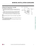
Страница 21: ... 3 16 to 5 16 from level with the slant being upward on the indoor unit side and downward on the outdoor unit side 2 Finish off the newly drilled hole as shown with bushing and sleeve covering Sleeve and bushing prevents damage to the tubing bundling of the piping 3 16 5 16 Indoor WALL Outdoor Bushing Core Drill Sleeve Figure 11 Drilling Piping Hole See Refrigerant Piping Connections for Indoor Un...

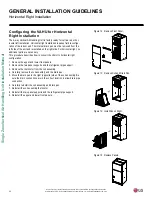
Страница 22: ...ntal right no additional parts are necessary This procedure describes how to convert the VAHU to horizontal right configuration 1 Remove the upper and lower front panels 2 Remove the two panel supports and the refrigerant pipe support 3 Remove the thermistor from the coil assembly 4 Carefully remove the coil assembly and the drain pan 5 Move the drain pan to the right opposite side of the coil ass...

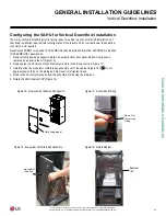
Страница 23: ...uired for 36 48MBH NK chassis units 1 Remove front panels and supports Retain all except bottom front panel Bottom front panel is replaced by a panel in the kit Figure 16 2 Remove pipe in and out sensors and temporarily store in the blower section Figure 17 3 Carefully slide the evaporator coil drain pan assembly out of the cabinet Figure 18 Do not apply excessive force on the piping as it may res...

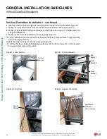
Страница 24: ...not left right hand dependent 9 Position the front horizontal bracket and secure with screws Figure 21 10 Confirm all bracket screws are secure and the bracket assembly is correctly positioned to support the evap orator coil drain pan assembly 11 Route the wiring for the pipe in and pipe out sensors Figure 22 12 Carefully slide the evaporator coil drain pan assembly back into the cabinet Figure 23...

Страница 25: ...ough the ring Figure 25 15 Reinstall the refrigerant pipe support bracket Figure 26 16 Reinstall the pipe in and pipe out sensors Figure 27 17 Reinstall all front panels Be sure to use the front panel included in the downflow kit Figure 28 Figure 24 Reinstall Support Bracket Cabinet Support Bracket Figure 25 Wiring Ring Plastic Ring Figure 26 Pipe Support Bracket Pipe Support Bracket Figure 27 Rei...

Страница 26: ...d it is man datory that the flexible connector between unit and duct at discharge connection is made of heat resistant material Duct work must be insulated and covered with vapor barrier when routed through unconditioned space To prevent the formation of condensation insulate the duct well Internal acoustical insulation lining may be necessary for the metal duct system if it does not have a 90 elb...

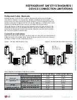
Страница 27: ...to refrigerant safety REFRIGERANT SAFETY STANDARDS DEVICE CONNECTION LIMITATIONS Connection Limitations Single zone systems consist of one outdoor unit and one indoor unit One of the most critical elements of a single zone system is the refrigerant piping Table 6 lists the pipe length limits that must be followed in the design of a Single Zone VAHU refrigerant pipe system Figure 31 LV181HV4 LV241H...

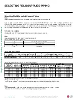
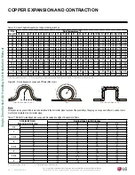
Страница 28: ...P Straight Lengths H58 Temper Coils O60 Temper Table 7 ACR Rated Copper Tubing Material OD in 1 4 3 8 1 2 5 8 3 4 7 8 1 1 8 1 3 8 1 5 8 Material Rigid or Soft ACR Rated for R410A Rigid or Solid ACR Rated for R410A Min Bend Radius in 0 563 0 9375 1 5 2 25 3 0 3 0 3 5 4 0 4 5 Min Wall Thickness in 0 03 0 03 0 03 0 03 0 03 0 03 0 03 0 04 0 050 Table 9 ACR Copper Tubing Dimensions and Physical Charact...

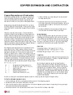
Страница 29: ...pansion distance Do the same for the maximum pipe temperature 3 Calculate the difference in the two expansion distance values The result will be the anticipated change in pipe length General Example A system is installed and the design shows that there is a 100 foot straight segment of tubing between an indoor unit and the outdoor unit In heating this pipe transports hot gas vapor to the indoor un...

Страница 30: ...0 80 0 85 0 90 0 95 1 00 1 05 1 10 1 08 1 15 1 30 1 40 1 45 1 50 120 0 48 0 48 0 60 0 72 0 78 0 84 0 90 0 96 1 02 1 08 1 14 1 20 1 26 1 32 1 30 1 38 1 56 1 68 1 74 1 80 140 0 56 0 56 0 70 0 84 0 91 0 98 1 05 1 12 1 19 1 26 1 33 1 40 1 47 1 54 1 51 1 61 1 82 1 96 2 03 2 10 160 0 64 0 64 0 80 0 96 1 04 1 12 1 20 1 28 1 36 1 44 1 52 1 60 1 68 1 76 1 73 1 84 2 08 2 24 2 32 2 40 180 0 72 0 72 0 90 1 08...

Страница 31: ...become clogged Refrigerant gas leaks shortages Refrigerant oil degradation Poor insulation of the compressor System does not operate properly Solutions Remove moisture from the piping Piping ends should remain capped until connections are complete Do not install piping on a rainy day Connect piping properly at the unit s side Remove caps only after the piping is cut the burrs are removed and after...

Страница 32: ...d compared to product design limitations In all cases materials must be suitable for the application and any applicable codes including but not limited to diameter and wall thick ness continuity per ACR standards Failure to do so may cause significant performance degradation Proper leak checks must be performed Using isolation valves does not automatically void any LG product warranty however a li...

Страница 33: ...pe insulation jacket Insulate the pipe first because pipe supports shall be installed outside around the primary pipe insulation jacket Clevis hangers must be used with shields between the hangers and insulation Field provided pipe supports must be designed to meet local codes If allowed by code use fiber straps or split ring hangers suspended from the ceiling on all thread rods fiber straps or sp...

Страница 34: ...inuous without any joints Underground refrigerant pipe must be located at a level below the frost line Table 13 Utility Conduit Sizes 1 OD pipe diameter in inches Values in parenthesis indicate OD of pipe with insulation jacket 2 Diameter of pipe with insulation Thickness of pipe insulation is typical Actual required thickness may vary based on surrounding ambient conditions and must be calculated...

Страница 35: ... ALWAYS create a 45 flare when working with R410A 1 Cut the pipe to length Measure the distance between the indoor unit and the outdoor unit Cut the pipes a little longer than measured distance 2A Remove the burrs Completely remove all burrs from pipe ends When removing burrs point the end of the copper pipe down to avoid introducing foreign materials in the pipe 2B Slide the flare nut onto the co...

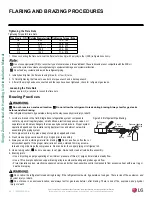
Страница 36: ...capillary tubes small orifices electronic expansion valves oil separators and heat exchangers that can easily become blocked Proper system operation depends on the installer using best practices and utmost care while assembling the piping system 2 Store pipe stock in a dry place keep stored pipe capped and clean 3 Flush clean all pipe sections with dry nitrogen prior to assembly 4 Always use a non...

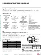
Страница 37: ...here to local codes regarding piping and accurate support spacing along the outdoor pipe line Always include plenty of insulation on all refrigerant and drain piping to ensure condensate does not form and cause damage to walls floors etc Pipe Bundling See the figure at right for proper pipe and cable bundling Note the place ment of the piping along with the necessary insulation material 1 Wrap eac...

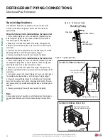
Страница 38: ...rom entering the control box 3 Secure the conduit piping set cover or bundle along the outside wall using saddles or a similar type of piping support 4 Seal any openings in the wall that are around the piping When the Outdoor Unit is Installed Above the Indoor Unit 1 Use a conduit piping set cover or bundle the separately insulat ed refrigerant piping and the communications connection power cable ...

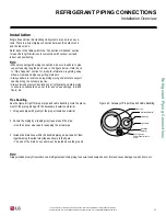
Страница 39: ...are before assembling Do not add any contaminants Tighten the flare nut initially by hand 5 Finish tightening the flare nut with a torque wrench until the wrench clicks Follow torque guidelines in the table below See figures for correct connection points Figure 44 LUU189HV LUU249HV Outdoor Unit Piping Connection When tightening the flare nut with a torque wrench ensure the direction for tightening...

Страница 40: ...tion system components contain very small capillary tubes small orifices elec tronic expansion valves oil separators and heat exchangers that can easily become blocked Proper system operation depends on the installer using best practices and utmost care while assembling the piping system 2 Store pipe stock in a dry place keep stored pipe capped and clean 3 Purge clean all pipe sections with dry ni...

Страница 41: ...ure any condensation will not damage walls floors etc Foamed polyeth ylene or equivalent at least 5 16 inches thick is recommended Downward slope to outdoor for proper drainage Indoor Unit Piping Correct Drainage Slope Figure 48 Drain Piping Upward slope to outdoor can cause indoor leaks Water leakage Accumulated drain water Ai r Waving Water leakage Indoor Unit Indoor Unit Incorrect Drainage Setu...

Страница 42: ... Typical Drain Pan Installation Figure 52 Piping with Insulation Material Figure 53 Correct Cutting Line Placement Figure 54 Wrapping Connection Pipe to Indoor Unit s Pipe Gas Pipe Liquid Pipe Cutting Line Cutting Line Correct Incorrect Vinyl tape narrow Connection pipe Connecting cable Vinyl tape wide Wrap with vinyl tape Indoor unit pipe Pipe Wrap with vinyl tape Drain hose Pipe Vinyl tape wide ...

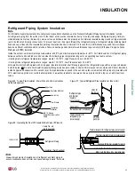
Страница 43: ...units consider the following pipe temperature ranges for an operating heat pump system Heating mode refrigerant temperature ranges Liquid 75 118 F High Pressure Vapor 95 220 F Cooling mode refrigerant temperature ranges Liquid 75 118 F Low Pressure Vapor 40 90 F All insulation joints shall be glued with no air gaps Insulation material shall fit snugly against the refrigeration pipe with no air spa...

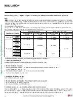
Страница 44: ...1 2 inch 1 2 inches 1 2 inches 1 2 inches 1 2 inches Vapor pipe ø3 8 inch 1 2 inches 3 4 inches 3 4 inches 1 inch ø1 2 inch ø5 8 inch ø3 4 inch ø7 8 inch ø1 inch ø1 1 8 inches 3 4 inches ø1 1 4 inches 1 inch 1 inch ø1 3 8 inches ø1 1 2 inches ø1 3 4 inches Table 16 Minimum Refrigerant Pipe EPDM Insulation Wall Thickness Requirements 1 Do not insulate gas and liquid pipes together as this can resul...

Страница 45: ...ely sized breakers fuses overcurrent protection switches and wiring in accordance with local state and National Electrical Code regulations related to electrical equipment and wiring and following the instructions in this manual Using an oversized breaker or fuse may result in electric shock physical injury or death Do not connect ground wire to refrigerant gas or water piping to lightning rods to...

Страница 46: ... bearing ring or fork terminals do not use galvanized or nickel plate over steel Use appropriate crimping tool to attach the ring or fork terminals at all power wiring and control cable terminations To install Firmly attach the wire secure in a way to prevent external forces from being imparted on the terminal block Use an appropriately sized JIS screwdriver for tightening the terminals Do not ove...

Страница 47: ...nd electrical shock which may cause physical injury or death Install appropriately sized breakers fuses overcurrent protection switches and wiring in accordance with local state and NEC regulation related to electrical equipment and wiring and following the instructions in this manual Generated overcurrent may include some amount of direct current Using an oversized breaker or fuse may result in e...

Страница 48: ...f shield ed the wire must be grounded to the chassis at the outdoor unit only Install insulation material as required by local code Firmly attach the cable provide slack but secure in a way to pre vent external forces from being imparted on the terminal block Wiring must be completed without splices Always verify the communication cable is connected to a commu nications terminal on the Single Zone...

Страница 49: ... plug PZCWRC1 sold separately that connects to the CN REMO terminal on the indoor unit PCB 2 Field supplied controller cable that connects to the indoor unit terminal block must be at least UL2547 or UL1007 and at least FT 6 rated if local electric and building codes require plenum cable usage Communication cable from indoor unit to remote controller s is to be 22 AWG 3 conductor twisted stranded ...

Страница 50: ...0 800 Table 17 ESP Setting Values NJ frame Installer settings available to change the CFM to 10 above or 10 below the values mentioned in the above table How to Enter Installer Setting Mode 1 Press button and button simultaneously for 3 seconds to enter the installer setting mode 2 When entering installer setting mode fuction code is displayed on the LCD screen 3 Press button to select function co...

Страница 51: ...0 65 71 79 86 92 96 102 106 114 _ Low 1 000 61 67 75 82 88 94 100 104 112 116 LVN480HV 48 000 High 1 400 77 82 87 94 100 102 106 110 116 _ Mid 1 260 70 77 83 90 96 98 104 108 114 116 Low 1 000 61 67 75 82 88 94 100 104 112 116 If the ESP is set incorrectly the air conditioning may malfunction To get the desired air flow and external static pressure combination use the setting value from the table ...

Страница 52: ...e green yellow ground cable Ground cable must be longer than the other wires Secure the cable onto the control board using the cable tie 5 Reinstall the control box cover 6 Reinstall the indoor unit upper front panel 7 If all other piping and electrical wiring to the outside unit has been completed at this stage the system can be turned on to test If the piping connections have not been completed ...

Страница 53: ...ath Air Conditioner Main Power Source Circuit Breaker Use a circuit breaker or time delay fuse Figure 74 Circuit Breaker Figure 75 Outdoor Unit Electrical Connections 1 Remove the front panel and or control cover from the outdoor unit 2 Before proceeding inspect all wiring inside the casing to be sure they are secure and have not come loose during transportation and installation of the outdoor uni...

Страница 54: ...fications may change without notification LG Electronics U S A Inc Englewood Cliffs NJ All rights reserved LG is a registered trademark of LG Corp ELECTRICAL SYSTEM INSTALLATION Indoor Unit Wiring Diagram LVN181HV4 LVN241HV4 LVN361HV4 Figure 76 Indoor Unit Wiring Diagram Wiring Diagram for LVN181HV4 LVN241HV4 LVN361HV4 7 19 ...

Страница 55: ...fications may change without notification LG Electronics U S A Inc Englewood Cliffs NJ All rights reserved LG is a registered trademark of LG Corp ELECTRICAL SYSTEM INSTALLATION Indoor Unit Wiring Diagram LVN420HV LVN480HV Figure 77 Indoor Unit Wiring Diagram Wiring Diagram for LVN420HV LVN480HV ...

Страница 56: ...nnovation some specifications may change without notification LG Electronics U S A Inc Englewood Cliffs NJ All rights reserved LG is a registered trademark of LG Corp ELECTRICAL SYSTEM INSTALLATION Outdoor Unit Wiring Diagram LUU189HV Figure 78 Outdoor Unit Wiring Diagram 7 19 Wiring Diagram for LUU189HV ...

Страница 57: ... specifications may change without notification LG Electronics U S A Inc Englewood Cliffs NJ All rights reserved LG is a registered trademark of LG Corp ELECTRICAL SYSTEM INSTALLATION Figure 79 Outdoor Unit Wiring Diagram 7 19 Wiring Diagram for LUU249HV Outdoor Unit Wiring Diagram LUU249HV ...

Страница 58: ...nnovation some specifications may change without notification LG Electronics U S A Inc Englewood Cliffs NJ All rights reserved LG is a registered trademark of LG Corp ELECTRICAL SYSTEM INSTALLATION Outdoor Unit Wiring Diagram LUU369HV Figure 80 Outdoor Unit Wiring Diagram 7 19 Wiring Diagram for LUU369HV ...

Страница 59: ...ications may change without notification LG Electronics U S A Inc Englewood Cliffs NJ All rights reserved LG is a registered trademark of LG Corp ELECTRICAL SYSTEM INSTALLATION Figure 81 Outdoor Unit Wiring Diagram Wiring Diagram for LUU428HV LUU488HV Outdoor Unit Wiring Diagram LUU428HV LUU488HV ...

Страница 60: ...t switch input Float switch sensing CN ZONE Zone controller Zone controller connection CN OPTION Optional PCB EPROM Option PCB connection CN EXT External ON OFF controller External ON OFF controller connection CN DISPLAY Display Display of indoor status CN CC Dry contact Dry Contact connection CN PIPE OUT RD Discharge pipe sensor Pipe out thermistor CN LEAK VI Refrigerant leak detector Refrigerant...

Страница 61: ...ation There would be reduction in heating capacity while defrosting or oil return operation Dip Switch Function Off On Description SW1 COMMUNICATION Off default _ _ SW2 CYCLE Off default _ _ SW3 GROUP CONTROL Master Slave Group control setting using 7 Day Programmable Controller selects Master Slave on each indoor unit SW4 DRY CONTACT MODE Variable Auto Sets operation mode for optional Dry Contact...

Страница 62: ...ntering the refrigerant system in a liquid state the top of the cylinder must be higher than its bottom used in a vertical standing position when the system is pressurized Use only a leak free gauge manifold set Piping system must not be pressured to more than 550 psi Pressures greater than 550 psi may damage the piping system and cause unit malfunction Triple Leak Pressure Check Procedure 1 After...

Страница 63: ... service valves must remain closed and the stem head access caps tight Do not open the outdoor unit service valves and release the factory refrigerant charge until trim charge is complete and the system is ready to operate Any field installed ball valves if used in the refrigerant system must be open to ensure all piping is free and clear for evacuation on all piping and connected indoor unit Trip...

Страница 64: ...ron continue to step 4 4 Break vacuum with 50 psig nitrogen purge for an appropriate amount of time this is to sweep moisture from piping 5 Purge nitrogen from the system until the pressure drops down to 1 to 3 psig 6 Evacuate to 1 000 micron level Isolate the pump by closing the manifold gauges and the vacuum pump valve and then watch the micron level Micron level may rise a bit but MUST eventual...

Страница 65: ... refer to its owner s manual To use a handheld controller with the VAHU a wall controller with an infrared receiver is required 1 The remote controller needs two AAA 1 5V batteries for operation Remove the battery cover from the back of the remote controller Push downward on the tab at the top of the battery cover and then lift up to remove 2 Insert the two new batteries Align batteries by the and...

Страница 66: ...using the refrigerant 4 Close the liquid line service valve all the way 5 Turn on the unit s power switch and start the cooling mode operation 6 Observe the pressure gauge reading When it changes 1 to 0 5 kg cm2 14 2 to 7 1 psig fully close the gas line valve and then immedi ately turn the unit off Pump down procedure is complete and all refrigerant must be collected into the outdoor unit Enabling...

Страница 67: ...the data to troubleshoot the system The air conditioning system must run for at least 15 20 minutes before data collected by SIMs 2 0 is valid for troubleshooting The free SIMs app must be correctly installed on the smart phone before using SIMs Some outdoor units have an LGMV extension cable accessed by removing the side handle cover If the outdoor unit does not have this extension cable access t...

Страница 68: ... Voltage EEV Mode Restart Timer Comp Mode EEV Indoor Info Tab Displays the following information Frequency Operation THM Mode REM Mode FAN EEV Air Temp Pipe in Pipe mid Pipe out Graph Info Tab This tab has three sub sections IDU Indoor Unit Temperature graph Displays IDU informa tion in graph format In formation displayed is for the IDU selected on the Main screen ODU Outdoor Unit Temperature and ...

Страница 69: ...f indoor and outdoor units and the SIMs app If two or more errors occur simultaneously the lower error code number is displayed first After error is resolved the error code does not display Error Codes Decoding the Error Display The first and second number on the LED indicates error number Ex ample 21 LED1 Green light 2x blink LED2 Red light 1x blink Error Code Nomenclature Definitions MICOM Non v...

Страница 70: ... 41 D Pipe Sensor INV is disconnected or shorted out 4X 1X 44 Outdoor Air Sensor is disconnected or shorted out 4X 4X 45 Middle thermistor of outdoor unit condenser coil is disconnected or shorted out 4X 5X 46 Outdoor unit suction line thermistor is disconnected or shorted out 4X 6X 48 Outdoor unit coil outlet liquid line thermistor is disconnected or shorted out 4X 8X 53 Communication failure fro...

Страница 71: ...tlanta GA ASHRAE Inc Information about ASHRAE Standard 15 2010 34 2010 and addenda current as of the date of this publication Take appropriate actions at the end of HVAC equipment life to recover recycle reclaim or destroy R410A refrigerant according to applicable US EPA rules Total System Refrigerant Charge To calculate the potential refrigerant concentration level RCL 1 Measure the occupied spac...

Страница 72: ...ts were secured to the structure using a combination of fixed and floating clamps and all wall penetrations were sleeved Pipe insulation was not compressed at any point No oil traps solenoid valves sight glasses filter driers or any other unauthorized refrigerant specialties were present Optional High quality R 410A rated full port ball valves Schrader between the valve body and the indoor units u...

Страница 73: ...NOTES ...
Страница 74: ...uals service manuals and catalogs visit www lghvac com LG Electronics U S A Inc Commercial Air Conditioning Division 4300 North Point Parkway Alpharetta Georgia 30022 www lg vrf com IM_SZ_VAHU_12_19 Supercedes IM_SZ_VAHU_12_17 20001747 ISO 9001 2008 LG ELECTRONICS INC ...

Отзывы: