


41
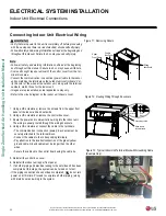
Refrigerant Piping Connections
Due to our policy of continuous product innovation, some specifications may change without notification.
©LG Electronics U.S.A., Inc., Englewood Cliffs, NJ. All rights reserved. “LG” is a registered trademark of LG Corp.
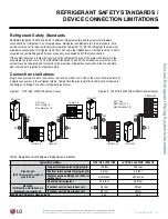
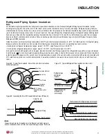
REFRIGERANT PIPING CONNECTIONS
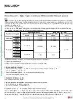
Drain Hose
Indoor Unit Drain Hose Guidelines
Refer to the diagrams below and follow proper
installation and the running of the drain hose
along the pipe installation line to avoid leak-
age. Once drain hose is set in place, always
follow with evacuation and leakage testing
of all piping to be sure all piping is properly
sealed. Re-check and retest as necessary.
Drain hose is routed from the indoor unit
through the structure (wall) to the outdoors.
It must slope at an angle where it is higher at
the indoor unit and lower toward the outdoor
area, thereby letting gravity push any conden-
sation down and out. Avoid piping the drain
hose as shown in Figure 50. These methods
are incorrect and can cause leaks at the
indoor unit site.
The drain hose may need to be extended so
that condensate can be properly routed away.
The drain hose extension must be correctly
insulated to ensure any condensation will not
damage walls, floors, etc. Foamed polyeth
-
ylene or equivalent at least 5/16 inches thick
is recommended.
Downward slope
to outdoor
for proper drainage
Indoor
Unit
Piping
Correct Drainage Slope
Figure 48: Drain Piping
Upward slope
to outdoor
can cause indoor
leaks!
Water
leakage
Accumulated
drain water
Ai r
Waving
Water
leakage
Indoor Unit
Indoor Unit
Incorrect Drainage Setup
Tip of drain hose
dipped in water
Water
leakage
Ditch
Less than
2 Inch gap from ground
Indoor Unit
Drain Hose
Figure 49: Correct Slope Angle
for the Drain Hose.
Figure 50: Incorrect Slope Angles for the Drain Hose.
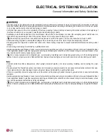
Drainage hole
U-Trap
B
C
A
≥
2-9/16 inch
B
≥
2C
C
≥
2 x SP
SP = External Pressure
(in.wc)
Ex) External Pressure
= 0.4 in. wc
A
≥
2-9/16 inch
B
≥
1-7/12 inch
C
≥
19/24 inch
A
Make sure to be closed.
Unit
Drainage pipe
(Field supply)
Thermal insulator
(Field supply)
Applied U-Trap Dimension
CORRECT
• Install the U-Trap to prevent water leaks
caused by a blocked intake air filter
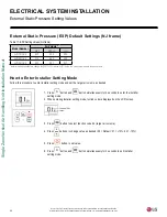
3/4 inch
connector
Horizontal-left
Drain Knockout
Air filter cover
Main drain along with suitable trap.
( Field supplied trap with sufficient
depth can be used. P-traps of standard
size are not sufficient. Refer to the figure
below for recommended condensate trap.)
Auxiliary drain
with proper trap. (field
supplied kit can be used)
Upflow Drain
Horizontal Left Drain
Insulate Drain Pipe
Содержание LV181HV4
Страница 73: ...NOTES ...