9. ENGINEERING MODE
- 111 -
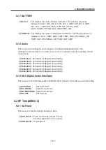
9.1.7 BATTERY
1) Bat Cal
:
This displays the value of Battery Calibration. The following menus are
displayed in order : BAT_LEV_4V, BAT_LEV_3_LIMIT, BAT_LEV_2_LIMIT,
BAT_LEV_1_LIMIT, BAT_IDLE_LI MIT, BAT_INCALL_LIMIT,
SHUT_DOWN_VOLTAGE, BAT_RECHARGE_LMT
2) TEMP Cal :
This displays the value of Temperature Calibration. The following menus are
displayed in order : TEMP_HIGH_LIMIT, TEMP_HIGH_RECHARGE_LMT,
TEMP_LOW_RECHARGE_LMT, TEMP_LOW_LIMIT
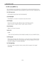
9.1.8 Audio
This is a menu for setting the control register of Voiceband Baseband Codec chip.
Although the actual value can be written over, it returns to default value after switching off and
on the phone.
1) VbControl1 :
VbControl1 bit Register Value Setting
2) VbControl2 :
VbControl2 bit Register Value Setting
3) VbControl3 :
VbControl3 bit Register Value Setting
4) VbControl4 :
VbControl4 bit Register Value Setting
5) VbControl5 :
VbControl5 bit Register Value Setting
6) VbControl6 :
VbControl6 bit Register Value Setting
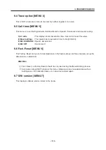
9.1.9 DAI (Digital Audio Interface)
This menu is to set the Digital Audio Interface Mode for Speech Transcoder and Acoustic testing.
1) DAI AUDIO
: DAI audio mode
2) DAI UPLINK
: Speech encoder test
3) DAI DOWNLINK
: Speech decoder test
4) DAI OFF
: DAI mode off
9.2 RF Test [MENU 2]
9.2.1 SAR test
This menu is to test the Specific Absorption Rate.
1) SAR test on :
Phone continuously process TX only.
Call-setup equipment is not required.
2) SAR test off :
TX process off
Содержание B2070
Страница 54: ... 53 4 TROUBLE SHOOTING 4 2 TX Trouble TEST POINT 13Mhz OSCILLATOR Mobile SW FEM TRANCEIVER LDO PAM ...
Страница 68: ... 67 4 TROUBLE SHOOTING TEST POINT 4 6 LCD Trouble ...
Страница 72: ... 71 4 TROUBLE SHOOTING TEST POINT 4 8 Speaker Trouble ...
Страница 79: ... 78 4 TROUBLE SHOOTING 4 11 KEY backlight Trouble TEST POINT ...
Страница 96: ...6 Press Start and Pover on the phone using JIG remote Power on Switch 1 5 DOWNLOAD AND CALIBRATION 95 ...
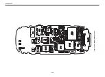
Страница 107: ... 106 8 PCB LAYOUT Figure 8 1 B2070 BOTTOM SIDE PCB LAYOUT ...
Страница 108: ... 107 8 PCB LAYOUT Figure 8 1 B2070 TOP SIDE PCB LAYOUT ...
Страница 109: ... 108 ...
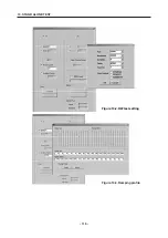
Страница 117: ...10 STAND ALONE TEST 116 Figure 10 2 HW test setting Figure 10 3 Ramping profile ...
Страница 121: ... 120 ...
Страница 123: ... 122 ...


