2. Guideline for each installation process
27
_
Heat pump 50Hz/R410A
Part 3 Design and installation
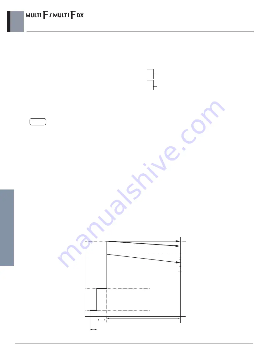
2.6.2 Essential points of testing
The key to successful testing is strict adherence to the following procedure:
1) The liquid and gas piping in each refrigerant system should be pressurized in turn in accordance with the following steps.
(Nitrogen gas must be used.)
Increasing the system pressure to 3.8MPa does not guarantee the identification of minor leaks if pressure is maintained for
only a short time. It is therefore recommended that the system remain pressurized in accordance with Step 3 above for at
least 24 hours.
Example:
During of pressurizing: 3.8MPa 25
˚
C
24 hours later: 3.75MPa 20
˚
C
Although the gauge pressure is dropped from 3.8MPa to 3.75MPa, it can be safely assumed that there is no leakage
because the gauge pressure can also drop due to the change in outdoor temperature.
Step 1: increase pressure to 0.3MPa for 3 minutes or more
Step 2: increase pressure to 1.5MPa for 3 minutes or more
Step 3: increase pressure to 3.8MPa for approxmate 24 hours
Major leaks indicate
Minor leaks indicate
3.8
3.75
3.5
3.0
2.5
2.0
1.5
1.0
0.5
0
3 minutes
5 minutes
24 hours
0.3MPa x 3min
1.5MPa x 5min
Step 1
Step 2
Step 3
3.8MPa x 24min
(MPa)
(Time)
25
Ƅ
15
Ƅ
20
Ƅ
Outdoor temperature(
Outdoor temperatu
re(
Ƅ(
Ƅ(
Outdoor temperature(
Ƅ(
Piping should not be pressured more than 3.8MPa.
2) Check for pressure drop
If there is no drop in pressure then the test is deemed a success.
If the pressure drops then the leak must be located. See following page.
However, if there is a change in the ambient temperature between the pressurizing stage and the time when you check for
a drop in pressure then you will have to adjust your calculations accordingly since a change of 1°C can account for a pres-
sure change of approximately 0.01MPa.
Compensating adjustment value:
(temperature at time of pressurizing – temperature at time of checking) x 0.01
NOTE
Содержание A4UW24GFA0
Страница 1: ...Heat pump 50Hz R410A 0CIM0 02E Replaces 0CIM0 02D ...
Страница 4: ...Part 1 General information 1 Model line up 2 Nomenclature 3 Appearance 4 Combination ...
Страница 290: ...BD Unit Distributor Box 1 Specifications 2 Dimensions 3 Piping Diagrams 4 Wiring Diagrams ...
Страница 367: ...Part 4 Special Part 1 Installation guide at the seaside 2 Seasonal wind and cautions in winter ...


