Diagnostic aids
3-11
5022-xxx
Hardware Tests
Panel Test
This test verifies the operator panel LCD function.
To run the Panel Test:
1.
Select HARDWARE TESTS from DIAGNOSTICS.
2.
Select Panel Test.
The Panel Test continually executes.
3.
Press Stop (
) to cancel the test.
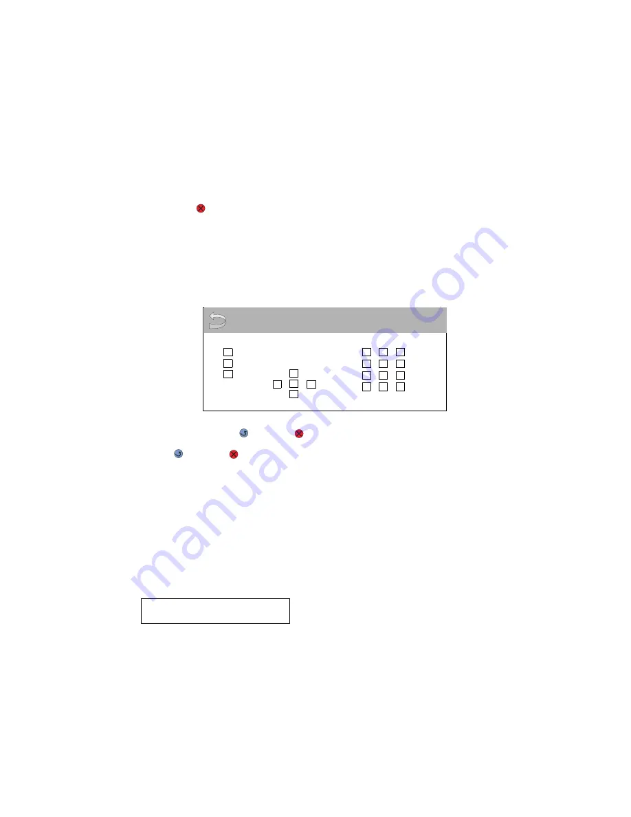
Button Test
This test verifies the operator panel button function.
To run the Button Test:
1.
Select Button Test from HARDWARE TESTS in the Diagnostics mode.
2.
Press each button one at a time, and an X appears in the box that represents that button.
When you press Back (
) or Stop (
), the test ends.
Press Back (
) or Stop (
) to cancel the test.
DRAM Test
This test checks the validity of DRAM, both standard and optional. The test writes patterns of data to DRAM to
verify that each bit in memory can be set and read correctly.
To run the DRAM Test:
Select DRAM Test from HARDWARE TESTS in DIAGNOSTICS. The power indicator blinks indicating the test is
in progress.
Note: Turn off the printer to exit the test before the test is complete.
P:###### represents the number of times the memory test has passed and finished successfully. Initially,
000000 displays with the maximum pass count being 99,999.
F:##### represents the number of times the memory test has failed and finished with errors. Initially, 00000
displays with the maximum fail count being 99,999.
Once the maximum pass count or fail count is reached, the test is stopped, the power indicator turns on solid,
and the final results appear. If the test fails, SDRAM Error appears for approximately three seconds and the
failure count increases by 1.
DRAM Test
128M
P:###### F:#####
Button Test
Содержание C52 series
Страница 13: ...Laser notices xiii 5022 xxx Japanese Laser Notice ...
Страница 14: ...xiv Service Manual 5022 xxx Korean Laser Notice ...
Страница 125: ...Diagnostic aids 3 31 5022 xxx ...
Страница 150: ...3 56 Service Manual 5022 xxx ...
Страница 164: ...4 14 Service Manual 5022 xxx Cover removals ...
Страница 177: ...Repair information 4 27 5022 xxx Installation note Be sure the tab B is fully engaged B ...
Страница 180: ...4 30 Service Manual 5022 xxx 9 Remove the linkage screw C C ...
Страница 184: ...4 34 Service Manual 5022 xxx 10 Remove the linkage screw C C ...
Страница 186: ...4 36 Service Manual 5022 xxx 13 Disconnect the ground cable J 14 Lift and remove the top access cover assembly J ...
Страница 256: ...4 106 Service Manual 5022 xxx ...
Страница 257: ...Locations and connectors 5 1 5022 xxx 5 Locations and connectors Locations Covers ...
Страница 259: ...Locations and connectors 5 3 5022 xxx Right EP drive assembly Bump aligner motor 5 V interlock switch ...
Страница 260: ...5 4 Service Manual 5022 xxx Rear ...
Страница 261: ...Locations and connectors 5 5 5022 xxx Left Toner level sensor Transfer contact assembly High voltage power supply ...
Страница 262: ...5 6 Service Manual 5022 xxx Top Top cover camshaft assembly Top access door 24V interlock switch with cable ...
Страница 263: ...Locations and connectors 5 7 5022 xxx CRU and FRUs ...
Страница 264: ...5 8 Service Manual 5022 xxx Sensors Toner level sensor Toner patch sensor TPS ...
Страница 265: ...Locations and connectors 5 9 5022 xxx Motors ...
Страница 266: ...5 10 Service Manual 5022 xxx Printer cards ...
Страница 267: ...Locations and connectors 5 11 5022 xxx Connectors System card network models C52x ...
Страница 268: ...5 12 Service Manual 5022 xxx System card non network models C52x ...
Страница 274: ...5 18 Service Manual 5022 xxx System card network models C53x ...
Страница 280: ...5 24 Service Manual 5022 xxx ...
Страница 282: ...6 2 Service Manual 5022 xxx ...
Страница 284: ...7 2 Service Manual 5022 xxx Assembly 1 Covers 15 1 2 3 4 9 5 8 10 12 13 14 6 7 11 ...
Страница 286: ...7 4 Service Manual 5022 xxx Assembly 2 Front ...
Страница 288: ...7 6 Service Manual 5022 xxx Assembly 3 Right ...
Страница 290: ...7 8 Service Manual 5022 xxx Assembly 4 Rear ...
Страница 292: ...7 10 Service Manual 5022 xxx Assembly 5 Left 1 2 3 ...
Страница 294: ...7 12 Service Manual 5022 xxx Assembly 6 Top 1 2 ...
Страница 296: ...7 14 Service Manual 5022 xxx Assembly 7 Customer replaceable units CRUs 3 4 1 2 5 6 2 ...
Страница 298: ...7 16 Service Manual 5022 xxx Assembly 8 Contact springs ...
Страница 300: ...7 18 Service Manual 5022 xxx Assembly 9 Cable parts packet ...
Страница 312: ...I 10 Service Manual 5022 xxx ...
Страница 313: ......
Страница 314: ......


