background image

GETTING STARTED

3

CONTENTS

2

© 2019 LEVOLOR

®

, Inc.

Getting Started: 

Product View ............................................................................................ 3
Tools and Fasteners Needed .................................................................. 4

Installation: 

Installation Overview ................................................................................5
Mount the Installation Brackets — Inside Mount ............................ 6 – 7
Mount the Installation Brackets — Outside Mount ......................... 7 – 9
Mount the Installation Brackets — Side Mount ..................................... 9
Install Batteries & Connect the Power Source ............................. 10 – 11
Install the Shading ..................................................................................12
Attach the Magnetic Hold-Down Brackets (Optional)  ................ 12 – 13

Operation:

Operate the Shading ..............................................................................13
Resetting the Shading ............................................................................ 14
Troubleshooting .............................................................................. 15 – 19

Care:

Removing the Shading .......................................................................... 20
Cleaning Procedures ..................................................................... 20 – 21

Warranty

 .................................................................................................21

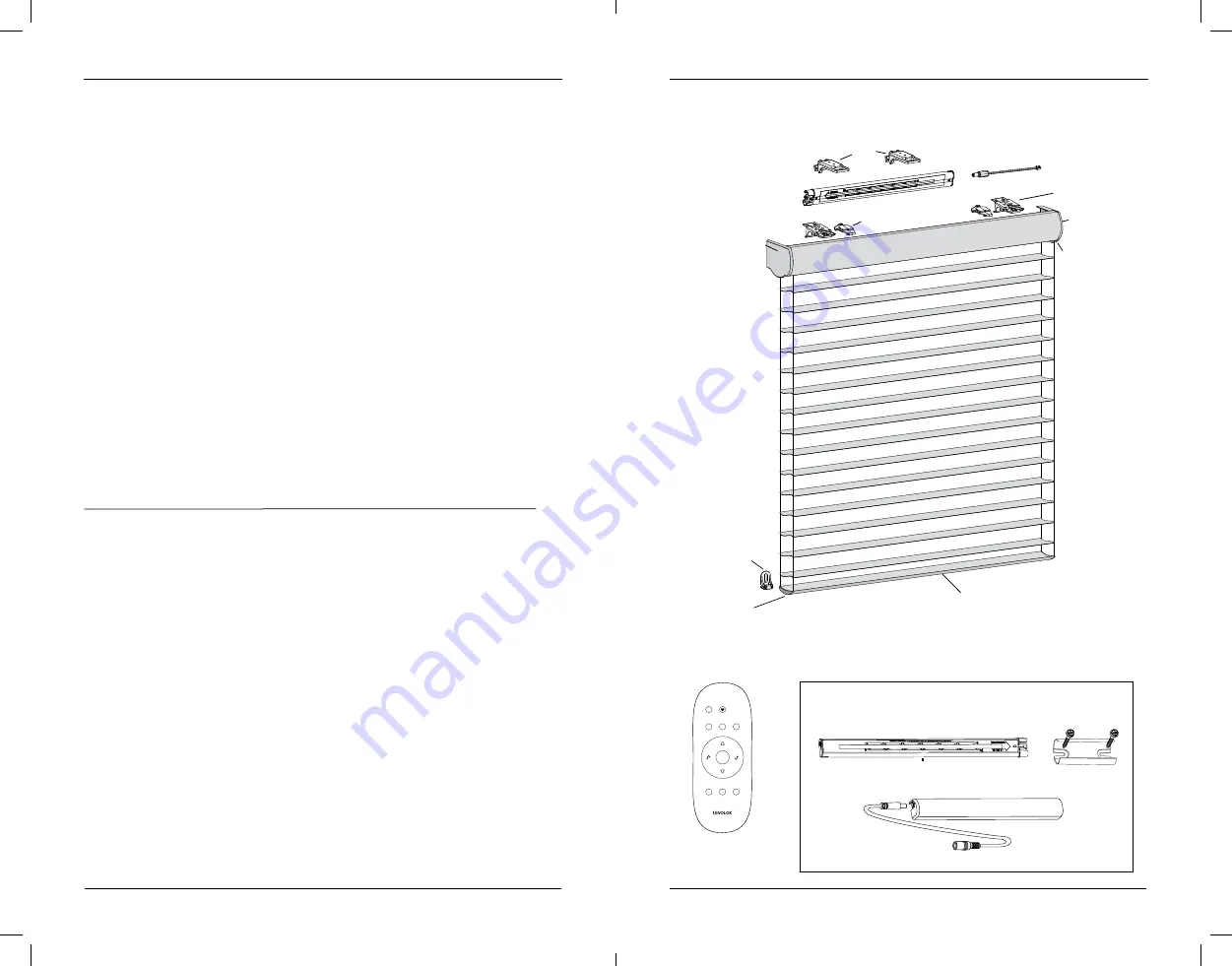
Product View

Remote 

(Optional)

Satellite Battery Pack 

(optional)

Satellite Battery Pack

Headrail

Headrail

End Cap

End Cap

Magnetic

Hold-Down

Bracket

(Optional)

Installation

Bracket

Limit Stop

Bottom Rail

Standard

Battery

Battery Pack

Clips

Battery Pack 

Cable

Manual 

Control

Button

ALL

1

2

3

4

5

6

Battery-Powered Motorized Operating System

Battery-Powered Motorized Operating System

Wall Mount Bracket

Battery Pack Cover

Extension

Cable

Socket

Radio Frequency FCC Compliance

This device complies with Part 15 of the FCC Rules. Operation is subject to the following two conditions: 

(1) This device may not cause harmful interference, and  

(2) This device must accept any interference received, including interference that may cause undesired operation.
This equipment has been tested and found to comply with the limits for a Class B digital device, pursuant to Part 15 of 

the FCC Rules. These limits are designed to provide reasonable protection against harmful interference in a residential 

installation. This equipment generates, uses and can radiate radio frequency energy and, if not installed and used 

in accordance with the instructions, may cause harmful interference to radio communications. However, there is no 

guarantee that interference will not occur in a particular installation. If this equipment does cause harmful interference 

to radio or television reception, which can be determined by turning the equipment off and on, the user is encouraged 

to try to correct the interference by one or more of the following measures:
•  Reorient or relocate the receiving antenna.

•  Increase the separation between the equipment and receiver.

•  Connect the equipment into an outlet on a circuit different from that to which the receiver is connected.

•  Consult the dealer or an experienced radio/TV technician for help.
Any changes or modifications not expressly approved by the party responsible for compliance could void the user’s 

authority to operate the equipment.

Industry Canada

Under Industry Canada regulations, this radio transmitter may only operate using an antenna of a type and maximum 

(or lesser) gain approved for the transmitter by Industry Canada. To reduce potential radio interference to other users, 

the antenna type and its gain should be so chosen that the equivalent isotropically radiated power (e.i.r.p.) is not more 

than that necessary for successful communication.
This device complies with Industry Canada licence-exempt RSS standard(s). Operation is subject to the following two 

conditions: (1) this device may not cause interference, and (2) this device must accept any interference, including 

interference that may cause undesired operation of the device.
Class B Digital Device Notice
This Class B digital apparatus complies with Canadian ICES-003, RSS-Gen and RSS-210.

Wall Mount 

Bracket

18-0053-026_Sheer_Motorized_Install_Guide_F_wu.indd   2-3

2/26/19   10:37 AM

Содержание Sheer Shadings

Страница 1: ...zado con bater a Syst me motoris aliment par pile Sheer Shadings Persianas trasl cidas Stores diaphanes INSTALLATION OPERATION CARE INSTALACI N FUNCIONAMIENTO CUIDADO INSTALLATION FONCTIONNEMENT ENTRE...

Страница 2: ...frequency energy and if not installed and used in accordance with the instructions may cause harmful interference to radio communications However there is no guarantee that interference will not occu...

Страница 3: ...heavy duty Power drill 3 32 drill bit and 1 4 hex driver In addition you will need fasteners designed to work with your specific mounting surface s 6 Hex Head Screws Provided Two 11 2 screws are provi...

Страница 4: ...Mount into wood whenever possible Allow a minimum of 18 from the motor side of the headrail and 15 between installation brackets to accommodate the standard battery pack See page 11 for standard batt...

Страница 5: ...wall If using extension brackets attach an installation bracket to the underside of each extension bracket using the speed nuts and screws provided Proceed to Install Batteries Connect to Power Source...

Страница 6: ...lation Damage or overheating of components could result Plug the Power Cable into the Battery Pack From the back of the shading headrail connect the power cable from the motor side into the socket on...

Страница 7: ...bracket height by loosening the screw and sliding the bracket up or down Operate the Shading Test the Shading Using the Manual Control Button Testing the shading with the manual control button will a...

Страница 8: ...securely connected to the power cable and the cables are not pinched or caught in the headrail or installation brackets See the Remote Control Guide for operating or programming troubleshooting soluti...

Страница 9: ...wer cable and the cables are not pinched or caught in the headrail or installation brackets Check that there is clearance between the ends of the shading and the window casement on inside mounts Check...

Страница 10: ...cessive or moves over time open the shading to its full vane open position and try again If this does not correct the problem reset the bottom limit See Resetting the Shading on page 14 See the Remote...

Страница 11: ...View Tab Installation Bracket Underside of Bracket End Cap Ultrasonic Cleaning Sheer shadings can be ultrasonically cleaned by a professional with the exception of light dimming fabrics Specify that...

Страница 12: ...Sistema de funcionamiento motorizado con bater a Persianas trasl cidas INSTALACI N FUNCIONAMIENTO CUIDADO 18 0053 026_Sheer_Motorized_Install_Guide_F_wu indd 22 23 2 26 19 10 37 AM...

Страница 13: ...ntra interferencias perjudiciales en una instalaci n residencial Este equipo genera utiliza y puede irradiar energ a de radiofrecuencia y si no se instala ni se usa de acuerdo con las instrucciones pu...

Страница 14: ...Consulte la secci n Soluci n de problemas en la p gina 38 si el funcionamiento de la persiana resulta dif cil o si el travesa o inferior gira alrededor del rollo de tela A continuaci n se muestran las...

Страница 15: ...NTE Los bordes frontales de las abrazaderas de instalaci n deben estar nivelados y alineados unos con otros Si utiliza bloques separadores apile los bloques separadores en la parte superior de las abr...

Страница 16: ...anel de yeso Si utiliza abrazaderas de extensi n fije una abrazadera de instalaci n a la parte inferior de cada abrazadera de extensi n con las tuercas de apriete r pido y los tornillos incluidos Cont...

Страница 17: ...del paquete de bater as Coloque el paquete de bater as con el tomacorriente hacia el extremo del motor de la persiana Presione el paquete de bater as hacia arriba en los sujetadores del paquete de ba...

Страница 18: ...o el tornillo y deslizando la abrazadera hacia arriba o hacia abajo Ajuste la abrazadera mediante el uso de la canaleta Abrazadera de fijaci n Riel inferior Cortinero Abrazadera de instalaci n Palanca...

Страница 19: ...talaci n Soluci n Compruebe que las abrazaderas de instalaci n est n niveladas y alineadas Si es necesario ajuste o calce el nivel Aseg rese de que las cabezas de los tornillos de montaje est n al ras...

Страница 20: ...ci n Compruebe que haya un espacio entre los extremos de la persiana y la secci n giratoria de la ventana en los montajes interiores Compruebe si la tela se enrolla de forma pareja en el cortinero Si...

Страница 21: ...letamente cerrada Si hay mucha distancia o se mueve con el tiempo abra la persiana a la posici n tabilla abierta totalmente y vuelva a intentarlo Si esto no corrige el problema restablezca el l mite d...

Страница 22: ...ta superior Leng eta Abrazadera de instalaci n Lado inferior de la abrazadera Tapa para los extremos Frente Tablillas 42 Sistema de funcionamiento motorizado con bater a CUIDADO Limpieza ultras nica U...

Страница 23: ...Syst me motoris aliment par pile Persianas trasl cidas INSTALLATION FONCTIONNEMENT ENTRETIEN 18 0053 026_Sheer_Motorized_Install_Guide_F_wu indd 44 45 2 26 19 10 38 AM...

Страница 24: ...t mettre de l nergie radiofr quence et s il n est pas install et utilis conform ment aux instructions risque de provoquer des interf rences nuisibles aux communications radio Cependant tout risque d i...

Страница 25: ...atre r glages de but e possibles pour les rouleaux de tissu du plus grand au plus petit sont indiqu s ci dessous Survol de l installation Le nombre ad quat de supports d installation pour la largeur d...

Страница 26: ...supports d installation doivent tre de niveau et align es Si vous utilisez des blocs espaceurs empilez les sur les supports d installation Fixez le support et les blocs espaceurs la surface de montage...

Страница 27: ...us utilisez des rallonges de support fixez un support d installation sur le c t inf rieur de chaque rallonge de support l aide des crous ressort et des vis fournis Passez l tape Installation des piles...

Страница 28: ...I CE De5 08cm 7 62cm De5 08cm 7 62cm Syst me motoris aliment par pile Installation d un bloc piles standard Insertion du bloc pile standard dans les attaches pour bloc piles Orientez le bloc piles et...

Страница 29: ...ers le bas Ajustez le support l aide de la rainure Support de retenue Traverse inf rieure Caisson Support d installation Levier Faites glisser le caisson entre le levier et le support 57 Syst me motor...

Страница 30: ...s ins re pas dans les supports d installation Solution V rifiez que les supports d installation sont de niveau et align s Au besoin ajustez les ou utilisez une cale pour les mettre de niveau Assurez v...

Страница 31: ...es extr mit s du store et le ch ssis de la fen tre V rifiez si le tissu s enroule de fa on uniforme dans le caisson Sinon consultez la section Ajustement du poids de la traverse inf rieure la page 62...

Страница 32: ...t et l arri re des faces du tissu Si cet espacement est excessif ou qu il change avec le temps ouvrez le store afin qu il soit en position lamelles ouvertes puis r essayez Si cela ne permet pas de cor...

Страница 33: ...on Dessous du support Embout Vue de face Lamelles 65 Syst me motoris aliment par pile ENTRETIEN Nettoyage aux ultrasons Les stores diaphanes peuvent tre nettoy s aux ultrasons par un nettoyeur profess...

Страница 34: ...Notes Notas Remarques Notes Notas Remarques 18 0053 026_Sheer_Motorized_Install_Guide_F_wu indd 66 67 2 26 19 10 38 AM...

Страница 35: ...2019 LEVOLOR Inc 3 Glenlake Parkway NE Atlanta GA 30328 2019605 18 0053 026 18 0053 026_Sheer_Motorized_Install_Guide_F_wu indd 68 2 26 19 10 38 AM...

Отзывы: