Leuze electronic LSIS 472i M45-I1 Скачать руководство пользователя страница 41

Extended configuration – Leuze electronic webConfig tool

Leuze electronic

LSIS 472i

41

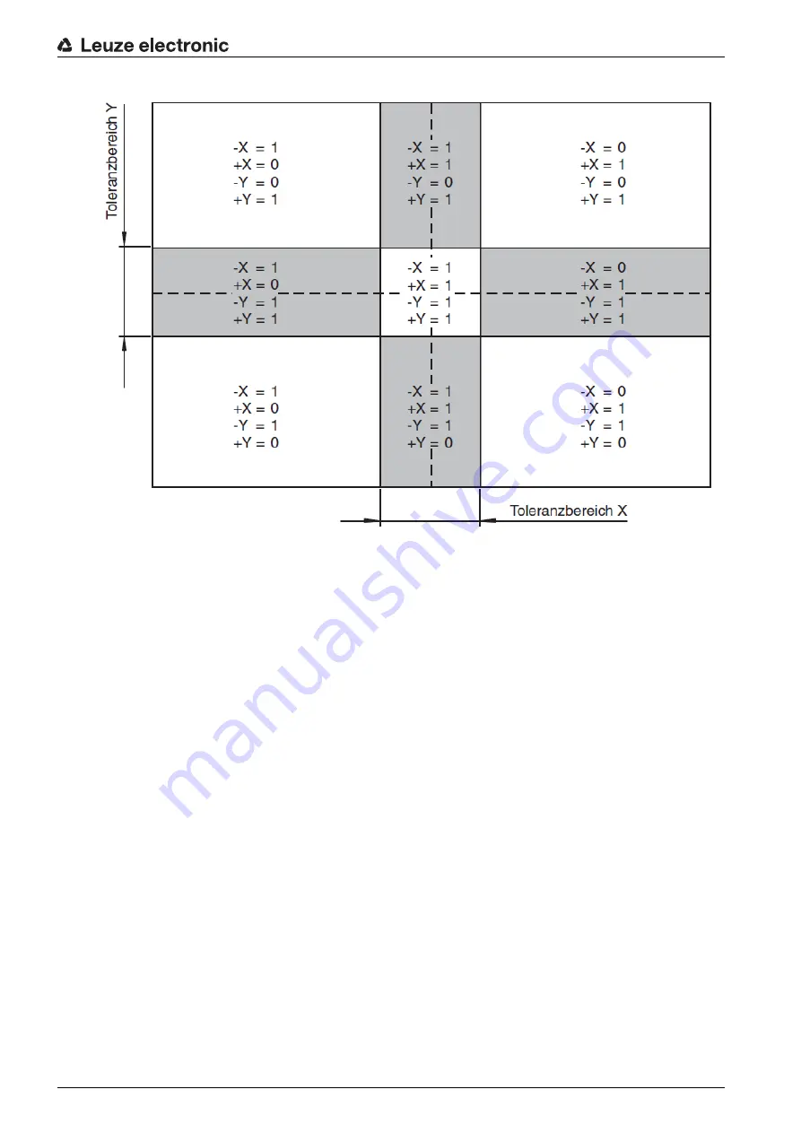
Figure 9.14: Switching of the switching outputs

9.3.12 Activating display of the target/actual deviation in the display

In order for the target/actual deviation for the marking to be shown in the display, the output must be acti

-

vated via the Ethernet interface.

Select 

CONFIGURATION > PROGRAMS

.

Select the active check program (

Rack Near

 or 

Rack Far

). 

Select 

CONFIGURATION > PROGRAM > Tools > Output > Display

.

The 

TOOL CONFIGURATION - Display 

dialog is displayed.

Содержание LSIS 472i M45-I1

Страница 1: ...LSIS 472i Smart camera for compartment fine positioning O r i g i n a l o p e r a t i n g i n s t r u c t i o n s EN 2015 05 50129066 We reserve the right to make technical changes...

Страница 2: ...Leuze electronic LSIS 472i 2 2015 Leuze electronic GmbH Co KG In der Braike 1 D 73277 Owen Germany Phone 49 7021 573 0 Fax 49 7021 573 199 http www leuze com...

Страница 3: ...agnostics image transfer 16 4 4 Process sequence 16 5 Applications 18 6 Mounting 19 6 1 Installation instructions 19 6 2 Mounting with BT 56 mounting device 19 6 3 Mounting with BT 59 mounting device...

Страница 4: ...l switching outputs the measurement values 39 9 3 12 Activating display of the target actual deviation in the display 41 9 3 13 Configuring the FTP output 42 9 3 14 Configuring the Ethernet output 44...

Страница 5: ...ext passages with this symbol provide you with further information Symbols for action steps Text passages with this symbol instruct you to perform actions BLOB Binary Large Object Hole or reflector fo...

Страница 6: ...sites for competent persons They have a suitable technical education They are familiar with the rules and regulations for occupational safety and safety at work They are familiar with the technical de...

Страница 7: ...e electronic GmbH Co KG is not liable in the following cases The device is not being used properly Reasonably foreseeable misuse is not taken into account Mounting and electrical connection are not pr...

Страница 8: ...in crossbeams in the rack construction and determines the position deviation in the X and Y direction relative to the target position The position deviation is output to the control via four digital o...

Страница 9: ...in the crossbeam of the rack is dependent on the working distance and the crossbeam Rack Near compartment fine positioning on hole or reflector Rack Far compartment fine positioning on reflector 3 1...

Страница 10: ...Reflectors for Rack Near and Rack Far compartment depths 3 1 4 Device model with heating The device is optionally available as a model with integrated heating In this case heating is permanently inst...

Страница 11: ...indicators Four control buttons Monochromatic display 1 LED PWR 2 Navigation buttons 3 LED BUS 4 Escape button 5 Enter button 6 Display Figure 3 3 Indicators and operational controls Ready made cable...

Страница 12: ...ns Set the desired option with the navigation buttons and the enter button 3 3 3 Display Display functions The following functions can be displayed and activated in the display Device information LED...

Страница 13: ...ng Lock and enable parameter entry on the display Define password for enabling parameter entry Reset parameters to factory settings Display settings Rotate the display 180 Only possible with enabled p...

Страница 14: ...472i 14 Display during device start up During device start up a start up display first appears which is briefly followed by the display with the version information After the device starts up the disp...

Страница 15: ...k Far check program is started or stopped via digital switching input I01 Figure 4 1 Display of the detected hole position Digital switching outputs IO5 IO8 signal whether the device is within the sca...

Страница 16: ...requisite The high bay storage device knows the hole positions for Rack Near and Rack Far Shortly before reaching the target position capture range a permanently applied signal at switching inputs IO2...

Страница 17: ...tion in ring buffer IO4 3 Program runs 4 State IO5 IO8 5 IO5 IO8 stable 6 Image transfer via FTP 7 3 Images that are written in the ring buffer 7 4 IO5 IO8 output inactive low 8 IO5 IO8 output active...

Страница 18: ...ed for the optical contactless compartment fine positioning of a high bay storage device in X and Y direction It is possible to use just one camera in single deep and double deep pallet high bay wareh...

Страница 19: ...tening grooves on the clamping jaws of the BT 59 with limit stop at end Secure the device with the M6 screw terminal NOTICE Observe during mounting Make certain that the required environmental conditi...

Страница 20: ...M6 screw terminal 8 Nm 6 4 BPS mounting with M4 fastening screws Mount the device on the system with M4 fastening screws not included in delivery contents Max tightening torque of the fastening screw...

Страница 21: ...N Safety Notices Before connecting the device please ensure that the supply voltage matches the value printed on the nameplate Only allow competent persons to perform the electrical connection The shi...

Страница 22: ...ss III for supply by PELV protective extra low voltage with reliable disconnection NOTICE Degree of protection IP 65 IP 67 Degree of protection IP 65 IP 67 is only achieved with screwed on connectors...

Страница 23: ...fine positioning Y 5 IO8 Configurable switching output 4 Compartment fine positioning Y 6 Rx Rx signal RS 232 7 Tx Tx signal RS 232 8 FE Functional earth Thread for M12 connector plug FE Connection c...

Страница 24: ...e connection cable is on the thread of the M12 connector plug The thread of the M12 connector plug is part of the metallic housing The housing is at the same poten tial as functional earth 2 1 3 4 1 8...

Страница 25: ...the display and control buttons see chapter 8 2 Mechanically aligning the device via the display Teach in the position of the smart camera see chapter 8 3 Teaching in the position Connect a PC laptop...

Страница 26: ...owards the semicircle 1 Marking indicator outside of capture range Figure 8 2 Marking in the field of view but not in the capture range A black dot in the position display indicates that the marking i...

Страница 27: ...t the Teach in menu Select Teach in If the Teach in menu option is crossed out in the Teach in menu teaching in of the position is not possible Mechanically realign the device see chapter 8 2 Mechanic...

Страница 28: ...ou must activate parameter enabling for the configuration settings via the display In the Parameter menu select the Parameter handling option Select the Parameter enable option Select the ON option an...

Страница 29: ...ss is printed can be separated from the remainder of the stick on label if necessary by means of the perforation To use the Address Link Label is peeled from the device and can be affixed in the insta...

Страница 30: ...your PC laptop 9 2 Start webConfig tool Prerequisite IP address and subnet mask for the LAN connection with the device are set correctly Connect the operating voltage to the device Connect the SERVIC...

Страница 31: ...connected to the control The process communication to the control is activated The switching inputs outputs are activated The configuration cannot be changed PROCESS function available CONFIGURATION f...

Страница 32: ...t fine positioning To commission more quickly you can set the most important parameters for the check programs Rack Near and Rack Far via a configuration dialog Alternatively you can make the configur...

Страница 33: ...ning accuracy X 5 mm Positioning accuracy Y 5 mm If the device sees the marking within an area of 25 mm x 25 mm around the center of the marking all switching outputs switch to 1 Enter the offset valu...

Страница 34: ...ing position of the high bay storage device If the offset values are 0 the smart camera positions the high bay storage device exactly on the marking If offset values are set the control signals a corr...

Страница 35: ...commissioning see chapter 9 3 4 you can make the configuration settings for compartment fine positioning manually Select CONFIGURATION PROGRAMS Select the active check program Rack Near or Rack Far S...

Страница 36: ...s of the application Under Binarization set the type of marking Hole Dark objects Reflector Bright objects BLOB attributes Select CONFIGURATION PROGRAM Tools BLOB Attributes The BLOB prefiltering dial...

Страница 37: ...NOMINAL limit values if the geometry of the marking has changed Centroid X Centroid Y attributes the limits of the centroid values must not be changed 9 3 8 Configuring the measurement Select CONFIGUR...

Страница 38: ...election ID 0 Near Rack If the Automatic program change checkbox is not selected the check program confirmation must be performed via a program change input Define the Delay time program selection inp...

Страница 39: ...witching inputs outputs 9 3 11 Assigning digital switching outputs the measurement values Check program specific assignment of tool results to the programmable digital switching outputs Select CONFIGU...

Страница 40: ...at is to be output via the switching output Click on the Save changes button The smart camera makes available digital switching outputs X X Y Y In addition the status of these switching outputs appear...

Страница 41: ...target actual deviation in the display In order for the target actual deviation for the marking to be shown in the display the output must be acti vated via the Ethernet interface Select CONFIGURATION...

Страница 42: ...dialog Select the Output activated checkbox Click on the Save changes button 9 3 13 Configuring the FTP output Check program specific output of test results on the Ethernet interface via the FTP prot...

Страница 43: ...ry if required by the FTP server for login Select the Fault image output at reading gate end checkbox Select the FTP activated checkbox Settings for the FTP connection Select CONFIGURATION PROGRAMS Se...

Страница 44: ...image name e g HBS1_rack1 The image name must not contain any space characters Image filing select the with time stamp option Click on the Save changes button 9 3 14 Configuring the Ethernet output C...

Страница 45: ...box Select Mode Server or Client If you select Client mode you must configure host communication Settings for the Ethernet output of target actual value deviation Select CONFIGURATION PROGRAM Select t...

Страница 46: ...ronic LSIS 472i 46 In the drop down lists select Tool Near measurement and Measurement Minimum Drag the Point 1 X and Point 1 Y functions into the Output for tool result OK or NOK field Click on the S...

Страница 47: ...vice see chapter 12 Orange contin uous light Device in Service mode Reset Service mode via webConfig or display Red continu ous light Internal device error Contact Leuze electronic customer ser vice s...

Страница 48: ...y the operator Repairs to the device must only be carried out by the manufacturer For repairs contact your responsible Leuze electronic subsidiary or Leuze electronic customer service see chapter 12 S...

Страница 49: ...ervice center Leuze electronic GmbH Co KG In der Braike 1 D 73277 Owen Germany 12 1 What to do should servicing be required Customer data please complete Leuze Service fax number 49 7021 573 199 NOTIC...

Страница 50: ...nd Diameter 10 mm 20 mm Near Rack minimum marking size 10 mm Far Rack minimum marking size 13 mm Operating voltage UB 18 30 VDC PELV Class 2 SELV Power consumption 8 W maximum Switching inputs 4 digit...

Страница 51: ...Fc Shock Continuous shock IEC 60068 2 27 test Ea IEC 60068 2 29 test Eb Electromagnetic compatibility EN 61000 6 2 EN 61000 6 4 Operating voltage UB 24 VDC 20 Devices with heating do not have UL appro...

Страница 52: ...Technical data Leuze electronic LSIS 472i 52 13 2 Dimensioned drawings all dimensions in mm Figure 13 1 Dimensioned drawing LSIS 472i 2 3 3 1...

Страница 53: ...00 BA PWR IO connection cable cable length 30 m IO DATA connection cable axial M12 plug 8 pin A coded open cable end Shielded for line lengths up to and including 10 m longer lengths unshielded 501101...

Страница 54: ...for field use inter faces RS 232 PROFIBUS DP 50114154 MA 235i Modular fieldbus connection for field use inter faces RS 232 CANopen 50114155 MA 238i Modular fieldbus connection for field use inter face...

Страница 55: ...rmity The LSIS 472i smart camera was developed and manufactured in accordance with the applicable Euro pean standards and directives The manufacturer of the product Leuze electronic GmbH Co KG in D 73...

Отзывы: