background image


Maintenance

Maintenance operations

7

 62

Lenze ¯ MA 12.0018 ¯  4.1

Version

Lubricants

CLP 460

CLP HC 320

CLP HC 220

USDA H1

Ambient temperature
[°C]

0 °C ... + 40

−25 °C ... + 50

−20 °C ... + 40

Specification

Mineral oil with additive

compounds

Synthetic oil (synthetic

hydrocarbon/poly−alpha−olefin oil)

Fuchs

Fuchs Renolin

CLP 460

Fuchs Renolin

Unisyn CLP 320

Klüber

Klüberoil

GEM1−460 N

Klübersynthl
GEM4−320 N

Klüberoil

4 UH1−220 N

Shell

Shell Omala

S2 G 460

Shell Omala

S4 GX HD 320

bremer & leguil

Cassida Fluid GL 220

7.3.3

Checking the oil level 

Note!

Check the oil level in cold condition!

Содержание g500-S130

Страница 1: ...Y Y Mounting Instruction EN g500 G50BS113 G50BS319 g500 S130 g500 S19000 130 Nm 19000 Nm Shaft mounted helical gearboxes Shaft mounted helical gearboxes with motor...

Страница 2: ...Please read these instructions before you start working Follow the enclosed safety instructions 0Abb 0Tab 0...

Страница 3: ...embly of drive systems 21 4 3 2 Gearboxes with breathers 22 4 3 3 Gearbox with compensation container preferably for mounting position M4 C 23 4 3 4 Mounting the gearboxes 24 4 3 5 Maximum permissible...

Страница 4: ...n 51 7 Maintenance 52 7 1 Important notes 52 7 2 Maintenance intervals 52 7 3 Maintenance operations 54 7 3 1 Position of the lubricant monitoring elements 55 7 3 2 Table of lubricants 61 7 3 3 Checki...

Страница 5: ...Qualified skilled personnel are persons who have the required qualifications to carry out all activities involved in installing mounting commissioning and operating the product Tip Information and too...

Страница 6: ...decimal point is always used For example 1234 56 Icons Page reference Reference to another page with additional information For instance 16 see page 16 Documentation reference Reference to another do...

Страница 7: ...gh dangerous electrical voltage Reference to an imminent danger that may result in death or serious personal injury if the corresponding measures are not taken Danger Danger of personal injury through...

Страница 8: ...technical modifications must never be operated unless completely assembled must never be operated without the covers guards can depending on their degree of protection have live movable or rotating pa...

Страница 9: ...100 C If these temperatures are exceeded measures are necessary to reduce the temperature 70 Danger Depending on the operating conditions surfaces may be hot provide protection against accidental cont...

Страница 10: ...Remove the plug for motors with condensation drain holes option 20 More than one year up to two years Apply a long term corrosion preventive e g Anticorit BW 366 by Fuchs to the shafts and uncoated su...

Страница 11: ...ction Only plug in or remove pluggable terminals in the deenergised state Commissioning If required you have to equip the system with additional monitoring and protective devices in accordance with th...

Страница 12: ...entation comply with the protection requirements of the EU Low Voltage Directive Any other use shall be deemed inappropriate 2 3 Foreseeable misuse Impermissible applications In a potentially explosiv...

Страница 13: ...fect shaft sealing ring on the A side Fuses are no motor protection Use current dependent motor protection switches at average operating frequency Use installed thermal detectors at high operating fre...

Страница 14: ...iption 3 1 Important notes The most important technical data is given on the nameplate The product catalogues contain further technical data 3 2 Short overview of the new mounting positions M1 A M2 D...

Страница 15: ...10 3 9 2 3 4 6 7 1 7 2 5 1 5 3 5 2 5 4 18 27 14 3 14 2 14 1 13 23 16 7 22 26 19 15 17 21 20 1 Geared motor with a directly mounted motor layout B with QR code L h cos j Hz kW r min V A 9 2 1 16 1 16 2...

Страница 16: ...11 10 1 10 3 10 2 20 1 L DE Asynchronous and synchronous servo motors L 1 15 11 2 4 5 5 5 8 5 2 5 4 5 3 5 6 5 9 5 10 16 6 22 5 7 14 2 14 1 27 14 3 9 12 8 1 18 10 2 10 3 8 2 8 3 Pos Contents 1 Manufact...

Страница 17: ...rovals and certificates 16 Rated data for various frequencies 16 16 1 Hz frequency 16 16 2 kW motor power 16 16 3 rpm motor speed 16 16 4 V motor voltage 16 16 5 A motor current 16 16 6 cos j motor po...

Страница 18: ...unting B Centering C Threaded pitch circle D Flange mounting Without flange R Flange with through holes K Number of stages 2 stage 2 3 stage 3 Motor mounting Integrated C IEC adapter N NEMA adapter A...

Страница 19: ...ad handling devices must at least correspond to the weight of the load Secure the load handling device so that it won t slip from its position The load must be secured in such a way that it cannot top...

Страница 20: ...ce of the tightening torque 10 Please note increase the tightening torque by 10 for screwed connections with flat gaskets Correcting the lubricant amount If the oil quantity in the gearbox has been in...

Страница 21: ...n must be plane torsionally rigid and free from vibrations must be suited to absorb the forces and torques generated during operation should have vibration absorbing properties Align drive system on m...

Страница 22: ...00 S130 G50BS113 und g500 S220 G50BS122 gearboxes do not require any ventilation measures Gearboxes that are delivered with a ventilation unit are provided with a label Remove the transport locking de...

Страница 23: ...rvoir Stop For transporting the geared motor the compensation reservoir must be removed and the gearbox must be locked by means of a locking screw Stop Leaky pipe to the oil compensation reservoir The...

Страница 24: ...level Gearbox with output flange Especially with regard to applications with an alternating load Lenze recommends the use of anaerobic adhesive between the gearbox flange and mounting area in order t...

Страница 25: ...orizontal acceleration force FMperm corresponds to the maximum value of the forces added vectorially L FM If the permissible force FMperm is exceeded the motor has to be supported in a suitable distor...

Страница 26: ...ters with clamping connection Important notes The transmission is made in a force fitting manner via a clamping connection Greases oils and other substances which reduce the friction factor reduce the...

Страница 27: ...ed Note Lenze recommends the use of smooth motor shafts without slots 7 Check If the drill depth in the hollow drive shaft is sufficient for the motor shaft For this purpose compare the drill depth fr...

Страница 28: ...4 Shaft surfaces 1 Gearbox degrease 2 Bell housing 3 Motor Mounting 1 Install the gearbox vertically so that the drive end is on top and securely fasten it 2 Locate the position of the mounting hole a...

Страница 29: ...screw 4 Afterwards insert the wrench 9 into the terminal screw 8 of the clamping ring 7 and leave it there Fig 7 The terminal screw 8 must only be tightened to such a degree that the clamping ring 7...

Страница 30: ...as not been tightened too much If required loosen it 6 Only when the flange of bell housing 2 and motor 3 lie flat on top of each other the fixing screws may be mounted for the motor screw strength at...

Страница 31: ...exible coupling When mounting a motor to an adapter be sure to observe a fully circumferential contact of the flange faces thus ensuring that there is no aperture to the interior of the adapter With h...

Страница 32: ...110 M10 69 M8 35 N2H 48 110 110 N3H 38 80 80 T51 24 50 50 M5 2 0 T55 28 60 60 T55 28 60 60 T61 38 80 60 M8 10 T65 42 110 111 T66 48 110 109 T70 55 110 110 T76 60 140 140 T81 2 65 140 140 M10 17 T82 7...

Страница 33: ...ed which is to be mounted The sizes concerned by this are shown on 32 2 With a clamping hub slightly loosen the clamping screw Fit coupling hub on the motor shaft using a center hole thread do not mou...

Страница 34: ...upling hub on the motor shaft using a center hole thread do not mount by hammer strokes in order to avoid damage to the roller bearings in the motor Observe mounting dimension m of the coupling hub se...

Страница 35: ...screw must only be loosened by half a revolution per pass Unscrew all clamping screws by 3 4 threads 2 Remove the screws next to the forcing threads and screw them into the other threads until they ha...

Страница 36: ...corrosion It does not have to be greased 1 Check whether the dimensions of the motor shaft and the featherkey match the hollow shaft bore and keyway 2 Check whether the drill depth in the hollow drive...

Страница 37: ...onnection Mounting of motors to gearboxes with a short adapter with a plug in hollow shaft with a keyway 4 37 Lenze MA 12 0018 4 1 the parts by hammer strokes 6 Screw the motor and gearbox flange toge...

Страница 38: ...in order to avoid unnecessary additional forces caused by tensioning 3 Apply a fitting grease LEERER MERKER to the shaft and into the hollow shaft bore 4 Mount gearbox with hollow shaft on the machine...

Страница 39: ...afts and keyway 4 39 Lenze MA 12 0018 4 1 K12 0611 Auxiliary tool recommended dimensions dH7 d2 c7 18 20 M6 4 25 30 M10 5 6 35 M12 7 40 45 50 M16 8 9 10 55 60 65 70 80 M20 11 13 13 14 16 90 100 120 M2...

Страница 40: ...ses a bearing failure and damage of the gearbox housing 1 Undo axial gearbox locking in the hollow shaft 2 Remove extract the gearbox from the motor shaft using an appropriate auxiliary tool LEERER ME...

Страница 41: ...170 G50BS195 g500 S950 143 60 180 G50BS221 g500 S2100 163 70 210 G50BS231 g500 S3100 188 80 240 G50BS245 g500 S4500 234 100 300 G50BS280 g500 S8000 260 135 350 G50BS314 g500 S14000 310 150 410 G50BS3...

Страница 42: ...tensioning 3 Thoroughly clean and degrease hollow shaft bore and machine shaft Note Thoroughly degrease the bore over the entire hollow shaft length to make sure that remainders of the anticorrosion...

Страница 43: ...5 40 Clamping screw thread M6 M5 M6 M6 M8 M6 M8 M6 M8 Width across flats SW1 mm 10 8 10 10 13 10 13 10 13 Torque Nm 12 6 14 14 30 14 30 14 34 Hollow shaft bore mm 50 65 75 80 95 105 125 Clamping screw...

Страница 44: ...er corresponding to the forcing threads in the inner ring For loosening the outer ring screw in the screws evenly to prevent canting Press off the outer ring until loosened completely 4 Remove the dri...

Страница 45: ...clipped on X X Clip the protection cover into the bores 6 x flange side 4 x motor side Gearbox size g500 S2100 G50BS221 g500 S19000 G50BS319 With these sizes the cover is screwed together with the ho...

Страница 46: ...the hole pattern on the foot see figure depending on the foot position Mounting order depending on the mounting situation and installation space the foot can first be screwed to the machine housing a...

Страница 47: ...the dimension Dc7 Tighten the screwed connection using 2 nuts to secure it Screws nuts and the fixing strap at the machine are not included in the scope of supply c7 c c6 c6 d 5 d D g50BS113 g50BS245...

Страница 48: ...5 1 Motor connection To correctly connect the motor please observe the notes in the terminal box of the motor the notes in the Operating Instructions of the motor the technical data on the motor namep...

Страница 49: ...emperature Ambient temperature 30 C 10 C Lubricant Food compatible oil CLP HC 46 USDA H1 Note When starting up a cold motor increased starting torques are to be expected at temperatures below 20 C due...

Страница 50: ...eds below 200 rpm the amount of lubricant may need to be increased Consultation with Lenze is required 6 3 Initial commissioning In order to ensure trouble free operation carry out checks during initi...

Страница 51: ...0 C Gearboxes with mineral oil CLP or for standard shaft sealing ring Use synthetic oil Provide for better cooling It may be necessary to contact Lenze 100 C Gearboxes with synthetic oil CLP HC and FK...

Страница 52: ...nameplate 7 2 Maintenance intervals Stop For drive systems Also observe the maintenance intervals for the other drive components Dust deposits prevent heat to be emitted and cause a high housing temp...

Страница 53: ...dust deposits To be inspected more frequently in the case of heavy dirt accumulation Check rubber buffer Check rubber buffer of the torque plate and replace it in the event of visible wear or damage R...

Страница 54: ...aintenance operations Gearboxes and geared motors are ready to use on delivery and filled by Lenze with the lubricant type and lubricant quantity indicated on the nameplate The first filling correspon...

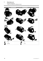
Страница 55: ...ents 7 55 Lenze MA 12 0018 4 1 7 3 1 Position of the lubricant monitoring elements g500 S130 g500 S660 G50BS113 G50BS166 Mounting position M1 A Mounting position M2 D Mounting position M3 B G50BS122 G...

Страница 56: ...ion of the lubricant monitoring elements 7 56 Lenze MA 12 0018 4 1 Mounting position M4 C Mounting position M5 F Mounting position M6 E G50BS140 G50BS166 G50BS122 G50BS122 G50BS113 G50BS113 G50BS113 G...

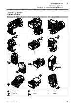
Страница 57: ...operations Position of the lubricant monitoring elements 7 57 Lenze MA 12 0018 4 1 g500 S950 g500 S4500 G50BS195 G50BS245 Mounting position M1 A Mounting position M2 D Mounting position M3 B Filling...

Страница 58: ...nce Maintenance operations Position of the lubricant monitoring elements 7 58 Lenze MA 12 0018 4 1 Mounting position M4 C Mounting position M5 F Mounting position M6 E G50BS231 Filling Drain Breathing...

Страница 59: ...osition of the lubricant monitoring elements 7 59 Lenze MA 12 0018 4 1 g500 S8000 g500 S19000 G50BS280 G50BS319 Mounting position M1 A Mounting position M2 D Mounting position M3 B 3 2 Filling Drain k...

Страница 60: ...tenance Maintenance operations Position of the lubricant monitoring elements 7 60 Lenze MA 12 0018 4 1 Mounting position M4 C Mounting position M5 F Mounting position M6 E Filling Drain Breathing Cont...

Страница 61: ...years Renolin CLP460 CLP Plus 460 Kl beroil GEM 1 460 N Omala S2 G460 Omala S2 GXV 460 CLP HC 220 30 C 40 C Synthetic oil with a poly alpha olefin basis 25000 h 4 years Renolin Unisyn CLP220 XT 220 K...

Страница 62: ...eral oil with additive compounds Synthetic oil synthetic hydrocarbon poly alpha olefin oil Fuchs Fuchs Renolin CLP 460 Fuchs Renolin Unisyn CLP 320 Kl ber Kl beroil GEM1 460 N Kl bersynthl GEM4 320 N...

Страница 63: ...3 Lenze MA 12 0018 4 1 Geared motor g500 S130 G50BS113 g500 S660 G50BS166 Check the oil level by means of the displayed dipsticks Manufacture them according to the mounting position Form template dips...

Страница 64: ...Maintenance Maintenance operations Checking the oil level 7 64 Lenze MA 12 0018 4 1 Form template dipsticks for g500 S220 G50BS122 100 mm 50 10 0 M1 M3 M4 M6 M2 M5...

Страница 65: ...Maintenance Maintenance operations Checking the oil level 7 65 Lenze MA 12 0018 4 1 Form template dipsticks for g500 S400 G50BS140 M1 M3 M6 M5 M2 M4 mm 100 50 10 0...

Страница 66: ...Maintenance Maintenance operations Checking the oil level 7 66 Lenze MA 12 0018 4 1 Form template dipsticks for g500 S660 G50BS166 mm 100 50 10 0 M1 M6 M3 M4 M2 M5...

Страница 67: ...t be below the threaded hole by the dimension x 4 Check gasket and replace it if necessary 5 Tighten oil control plug d2 G X 90 L Fig 19 Oil level in the gearbox housing Oil check bore hole Auxiliary...

Страница 68: ...xxx USDA H1 gearbox oil The oil drainage holes do not allow for complete draining of the gearbox in all cases Then a residual amount of oil remains in the gearbox If a change over to a food compatible...

Страница 69: ...n Depending on the mounting position the condensation drain holes are always at the bottom of the motor For condensate drainage the motor must be deenergised the plugs screws must be removed Stop To r...

Страница 70: ...que has not been reached Insufficient number of passes not all screws are tightened correctly Machine shaft and hollow shaft bore not sufficiently degreased Wrong component part dimensions Fits roughn...

Страница 71: ...03 2021 MA 12 0018 Y 4 1 TD09 Lenze SE Postfach 101352 31763 Hameln Hans Lenze Stra e 1 31855 Aerzen GERMANY Hannover HRB 204803 49 5154 82 0 49 5154 82 2800 sales de lenze com www lenze com...

Отзывы: