Mechanical installation
Mounting of g500 short/servo adapters with clamping connection
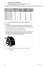
Maximum permissible load at the motor adapter
30
Lenze ¯ MA 12.0018 ¯ 4.1
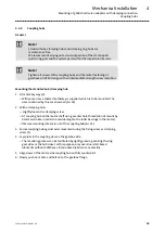
Note!
Lenze recommends the use of smooth motor shafts without slots!
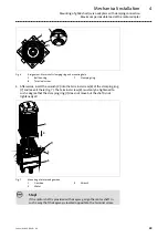
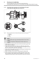
5. Position the motor shaft vertically and centrically to the hollow drive shaft and
insert it carefully into the hollow drive shaft. Exert only little force in order to
prevent damage to the ball bearing in the bell housing and the motor. Never
assemble the parts by applying blows! If it is difficult to put the parts together,
check if the terminal screw (8) has not been tightened too much. If required,
loosen it.
6. Only when the flange of bell housing (2) and motor (3) lie flat on top of each
other, the fixing screws may be mounted for the motor (screw strength at least
8.8, tightening torques according to strength 8.8). Secure the screw connections
with medium−strength screw locking adhesive.
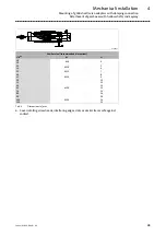
7. Tighten terminal screw (8). Tightening torque according to table ±10%.
Screw
Width across flats
Tightening torque
[mm]
[mm]
[Nm]
M5
4
6
M6
5
10
M8
6
25
8. Close the mounting hole in the bell housing (2) with the plug (5).
9. Install the geared motor into the machine / system.
–
Correct mechanical fixing and a professionally implemented electrical
connection must be ensured.
10.Perform a test run;
–
Pay attention to unusual noises and vibrations.
–
Overheating is not permissible!

