background image

ThinkServer
Hardware Maintenance Manual

ThinkServer TS200v Types 0981, 0992, 1008, and 1010

Содержание ThinkServer TS200v 1008

Страница 1: ...ThinkServer Hardware Maintenance Manual ThinkServer TS200v Types 0981 0992 1008 and 1010 ...

Страница 2: ......

Страница 3: ...ThinkServer Hardware Maintenance Manual ThinkServer TS200v Types 0981 0992 1008 and 1010 ...

Страница 4: ...ave been developed exclusively at private expense and are sold to governmental entities as commercial items as defined by 48 C F R 2 101 with limited and restricted rights to use reproduction and disclosure LIMITED AND RESTRICTED RIGHTS NOTICE If products data computer software or services are delivered pursuant a General Services Administration GSA contract use reproduction or disclosure is subje...

Страница 5: ...talling or replacing a PCI card 32 Replacing the battery 35 Installing or replacing a memory module 36 Installing or replacing the optical drive 38 Replacing the secondary hard disk drive 40 Replacing the power supply assembly 43 Replacing the heat sink and fan assembly 44 Replacing the microprocessor 45 Replacing the system board 47 Replacing the primary hard disk drive 50 Replacing the front fan...

Страница 6: ...tatement 90 Japanese compliance for products less than or equal to 20 A per phase 90 Federal Communications Commission FCC and telephone company requirements 90 Canadian Department of Communications certification label 91 Power cord notice 91 Polyvinyl Chloride PVC cable and cord notice 93 Turkish statement of compliance 93 Waste electrical and electronic equipment WEEE notices 93 European Union E...

Страница 7: ...s available at http www lenovo com support Before servicing a Lenovo product be sure to read the Safety Information See Important Safety Information on page 1 For information about the terms of the warranty and getting service and assistance see the Warranty and Support Information document Important Safety Information Be sure to read all caution and danger statements in this book before performin...

Страница 8: ... or perform installation maintenance or reconfiguration of this product during an electrical storm Connect all power cords to a properly wired and grounded electrical outlet Connect to properly wired outlets any equipment that will be attached to this product When possible use one hand only to connect or disconnect signal cables Never turn on any equipment when there is evidence of fire water or s...

Страница 9: ...optic devices or transmitters are installed note the following Do not remove the covers Removing the covers of the laser product could result in exposure to hazardous laser radiation There are no serviceable parts inside the device Use of controls or adjustments or performance of procedures other than those specified herein might result in hazardous radiation exposure DANGER Some laser products co...

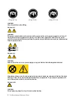
Страница 10: ...evice ensure that all power cords are disconnected from the power source 1 2 Statement 8 CAUTION Never remove the cover on a power supply or any part that has the following label attached Hazardous voltage current and energy levels are present inside any component that has this label attached There are no serviceable parts inside these components If you suspect a problem with one of these parts co...

Страница 11: ...rt numbers with the same fit and function are identified with unique FRU part numbers Lenovo plans to transition to RoHS compliance well before the implementation date and expects its suppliers to be ready to support Lenovo s requirements and schedule in the EU Products sold in 2005 will contain some RoHS compliant FRUs The following statement pertains to these products and any product Lenovo prod...

Страница 12: ...6 ThinkServerHardware Maintenance Manual ...

Страница 13: ...l machine types supported by this publication Features and specifications The following information is a summary of the features and specifications of the server Depending on the server model some features might not be available or some specifications might not apply Copyright Lenovo 2010 7 ...

Страница 14: ...ntel Active Management Technology AMT Intel Hyper Threading technology some models Intel Rapid Storage Technology RST Preboot Execution Environment PXE System Management SM UEFI and SM software Wake on LAN Wake on Ring in the Setup Utility program this feature is called Serial Port Ring Detect for an external modem Input Output I O features Eight Universal Serial Bus USB connectors two on the fron...

Страница 15: ...imum 200 V ac Maximum 240 V ac Input frequency range 50 to 60 Hz Voltage selection switch setting 230 V ac Software Lenovo provides software to help get your server up and running EasyStartup The ThinkServer EasyStartup program simplifies the process of installing supported Microsoft Windows operating systems and device drivers on your server The EasyStartup program is provided with your server on...

Страница 16: ...10 ThinkServerHardware Maintenance Manual ...

Страница 17: ...r readable instructions or a main menu on the display If you did not receive the correct response proceed to step 6 on page 11 If you do receive the correct response proceed to step 7 on page 11 6 Look at the following conditions and follow the instructions If you hear beep codes during POST go to Beep symptoms on page 16 If the server displays a POST error go to POST error codes on page 17 If the...

Страница 18: ...if they 1 Are the exact machine type and models 2 Have the same BIOS level 3 Have the same adapters attachments in the same locations 4 Have the same address jumpers terminators cabling 5 Have the same software versions and levels 6 Have the same diagnostic diskettes version 7 Have the same configuration options set in the system 8 Have the same setup for operating system controlled files Comparin...

Страница 19: ...ble CD DVD image known as an ISO image of the diagnostic program from http www lenovo com support 2 Use any CD DVD burning software to create a diagnostic disc with the ISO image Running the diagnostic program from a diagnostic disc This section provides instructions on how to run the diagnostic program from a diagnostic disc that you created To run the diagnostic program from a diagnostic disc th...

Страница 20: ... more tests do the following 1 Open the corresponding test category 2 Using the cursor movement keys highlight the desired test 3 Press the space bar A selected test is marked by Pressing the space bar again de selects a test and removes the 4 Repeat steps 2 and 3 above to select all desired tests Test results Diagnostics test results produce the following error code format Function Code Failure T...

Страница 21: ...rase Hard Drive utility do the following 1 Select the UTILITY option on the toolbar and press Enter 2 Select either the QUICK ERASE or FULL ERASE HARD DISK option and follow the instructions on the screen Viewing the test log Errors reported by the diagnostic test will be displayed by the program as a failed test To view details of a failure or to view a list of test results use the following proc...

Страница 22: ...s Microprocessor s connection Reseat connectors Check the power cord for continuity Power cord Check the power on switch for continuity Power on switch Beep symptoms Beep symptoms are tones or a series of tones separated by pauses intervals without sound during POST The following tables describes beep symptoms Beep Symptom FRU Action 2 short beeps CMOS setting error Perform the following actions i...

Страница 23: ...ests that check the operation of the system and some options This series of tests is called the Power On Self Test or POST POST does the following operations Checks some basic system board operations Checks the memory operation Starts the video operation Verifies that the boot drive is working If the POST detects a problem an error message appears on the screen A single problem can cause several e...

Страница 24: ...Non System disk or disk error Replace and press any key when ready The BIOS was unable to find a suitable boot device Make sure the boot drive is properly connected to the computer Make sure you have bootable media EasyStartup problems The following table describes the EasyStartup problems and suggested actions to correct detected problems Table 2 ThinkServer EasyStartup DVD Follow the suggested a...

Страница 25: ...ll not RPL from server 1 Ensure that network is in startup sequence as first device or first device after diskette 2 Ensure that network adapter is enabled for RPL 3 Network adapter Advise network administrator of new MAC address Computer will not perform a Wake On LAN if applicable 1 Check power supply and signal cable connections to network adapter 2 Ensure that the operating system settings are...

Страница 26: ...ms 1 Printer 2 System Board Program loads from the hard disk with a known good diagnostics diskette in the first 3 5 inch diskette drive 1 Run the Setup Utility program and check Startup sequence 2 Diskette Drive 3 Diskette Drive Cable 4 System Board 5 Power Supply RPL computer cannot access programs from its own hard disk 1 If network administrator is using LCCM Hybrid RPL check startup sequence ...

Страница 27: ...a External devices modem printer or mouse b Any adapters c Memory modules d Extended video memory e External Cache f External Cache RAM g Hard disk drive h Diskette drive 3 Turn on the server to re test the system 4 Repeat steps 1 through 3 until you find the failing device or adapter If all devices and adapters have been removed and the problem continues replace the system board Chapter 4 Diagnos...

Страница 28: ...22 ThinkServerHardware Maintenance Manual ...

Страница 29: ...he controls and connectors on the front of your server Figure 1 Front control and connector locations 1 Hard disk drive activity LED 3 Power switch 2 Power on LED 4 USB connectors 2 Rear view Rear connector locations shows the locations of the connectors on the rear of your server Some connectors on the rear of your server are color coded to help you determine where to connect the cables in your s...

Страница 30: ...nd audio signals from the server to external devices such as powered stereo speakers speakers with built in amplifiers headphones multimedia keyboards or the audio line in connector on a stereo system or other external recording device DisplayPort connector Used to attach a high performance monitor a direct drive monitor or other devices that use a DisplayPort connector Ethernet connector Used to ...

Страница 31: ...r locations on page 25 shows the locations of the parts and connectors on the system board Figure 3 System board connector locations 1 4 pin power connector 11 eSATA connector 2 Microprocessor 12 Power fan connector 3 Microprocessor fan connector 13 Front panel connector 4 DIMM 2 14 Clear CMOS Complementary Metal Oxide Semiconductor Recovery jumper 5 DIMM 1 15 Front USB connectors 2 6 DIMM 4 16 PC...

Страница 32: ...he inside of the server see Removing the server cover on page 30 Figure 4 Component locations 1 Heat sink 7 Secondary hard disk drive installed in some models 2 Microprocessor8 8 Primary hard disk drive 3 Memory modules 9 System board 4 Optical drive 10 Rear fan assembly 5 Front bezel 11 Power supply 6 Front fan assembly 26 ThinkServerHardware Maintenance Manual ...

Страница 33: ...hment of non Lenovo features or options that are not addressed in this section If you identify an unsafe condition you must determine how serious the hazard is and whether you must correct the problem before you work on the product Consider the following conditions and the safety hazards that they present Electrical hazards especially primary power Primary voltage on the frame can cause serious or...

Страница 34: ...tall main units Before you work on the equipment disconnect the power cord If you cannot disconnect the power cord have the customer power off the wall box that supplies power to the equipment and lock the wall box in the off position Never assume that power has been disconnected from a circuit Check it to make sure that it has been disconnected If you have to work on equipment that has exposed el...

Страница 35: ...c protective package touch it to an unpainted metal part on the outside of the server for at least 2 seconds This drains static electricity from the package and from your body Remove the device from its package and install it directly into the server without setting down the device If it is necessary to set down the device put it back into its static protective package Do not place the device on t...

Страница 36: ...is manual on page 1 and the Safety Information book To obtain a copy of the Safety Information book go to http www lenovo com support This section provides instructions on how to remove the server cover CAUTION Turn off the server and wait three to five minutes to let the server cool before removing the server cover To remove the server cover do the following 1 Remove any media from the drives and...

Страница 37: ... provides instructions on how to remove and reinstall the front bezel To remove and reinstall the front bezel do the following 1 Remove all media from the drives and turn off all attached devices and the server Then disconnect all power cords from electrical outlets and disconnect all cables that are connected to the server 2 Remove the server cover See Removing the server cover on page 30 3 Remov...

Страница 38: ... To obtain a copy of the Safety Information book go to http www lenovo com support This section provides instructions on how to install or replace a PCI card Your server has two standard PCI card slots one PCI Express x1 card slot and one PCI Express x16 card slot To install or replace a PCI card do the following 1 Remove all media from the drives and turn off all attached devices and the server T...

Страница 39: ...d latch 4 If you are installing a PCI card remove the appropriate metal slot cover If you are replacing an old PCI card grasp the old card that is currently installed and gently pull it out of the slot Chapter 6 Replacing FRUs 33 ...

Страница 40: ...from its static protective package 6 Install the new PCI card into the appropriate slot on the system board See System board internal connectors on page 25 Note If you are installing a PCI Express x16 card make sure the memory slot retaining clips are closed before you install the PCI Express x16 card 7 Pivot the PCI card latch to the closed position to secure the PCI card 34 ThinkServerHardware M...

Страница 41: ...ttery keeps this information active when you turn off the server The battery normally requires no charging or maintenance throughout its life however no battery lasts forever If the battery fails the date time and configuration information including passwords are lost An error message is displayed when you turn on the server To replace the battery do the following 1 Remove all media from the drive...

Страница 42: ...Attention Do not open your server or attempt any repair before reading and understanding the Chapter 1 About this manual on page 1 and the Safety Information book To obtain a copy of the Safety Information book go to http www lenovo com support This section provides instructions on how to install or replace a memory module Your server has four slots for installing or replacing memory modules When ...

Страница 43: ...o remove the PCI Express x16 card for easier access to the memory slots See Installing or replacing a PCI card on page 32 6 If you are installing a new memory module open the retaining clips of the memory slot into which you want to install the new memory module Figure 12 Opening the retaining clips If you are replacing an old memory module open the retaining clips and gently pull the memory modul...

Страница 44: ...rver Then disconnect all power cords from electrical outlets and disconnect all cables that are connected to the server 2 Remove the server cover See Removing the server cover on page 30 3 Remove the front bezel See Removing and reinstalling the front bezel on page 31 4 Depending on whether you are installing or replacing an optical drive do one of the following If you are installing a secondary o...

Страница 45: ...l drive retainer on the side of the new optical drive Figure 16 Installing the optical drive retainer 6 Slide the new optical drive into the optical drive bay from the front of the server until the optical drive snaps into position Chapter 6 Replacing FRUs 39 ...

Страница 46: ...tion book go to http www lenovo com support This section provides instructions on how to replace the secondary hard disk drive Installing a secondary hard disk drive To install a secondary hard disk drive do the following 1 Remove all media from the drives and turn off all attached devices and the server Then disconnect all power cords from electrical outlets and disconnect all cables that are con...

Страница 47: ...n 1 pin 2 pin 3 and pin 4 on the bracket with the corresponding holes in the hard disk drive Do not touch the circuit board 5 on the bottom of the hard disk drive Note If you are installing a 2 5 inch hard disk drive install the hard disk drive into a 2 5 inch to 3 5 inch hard disk drive tray first and then install the tray into the blue bracket Figure 19 Installing the hard disk drive into the br...

Страница 48: ...erneath the metal tab 1 Figure 20 Installing the secondary hard disk drive 10 Press the hard disk drive cage downward until it snaps into position Make sure that the hard disk drive cage is secured in the chassis Figure 21 Installing the secondary hard disk drive 42 ThinkServerHardware Maintenance Manual ...

Страница 49: ... See Removing the server cover on page 30 3 Disconnect the power supply assembly cables from the system board and all drives See System board internal connectors on page 25 4 Lay the server on its side and remove the four screws at the rear of the chassis that secure the power supply assembly Figure 22 Removing the screws for the power supply assembly 5 Slide the power supply assembly to the front...

Страница 50: ...s from electrical outlets and disconnect all cables that are connected to the server 2 Remove the server cover See Removing the server cover on page 30 3 Lay the server on its side for easier access to the system board 4 Locate the heat sink and fan assembly See System board internal connectors on page 25 5 Disconnect the heat sink and fan assembly cable from the microprocessor fan connector on th...

Страница 51: ...ur screws to secure the heat sink and fan assembly as shown in Removing the heat sink and fan assemblyFigure 23 on page 45 a Partially tighten screw 1 then fully tighten screw 2 and then fully tighten screw 1 b Partially tighten screw 3 then fully tighten screw 4 and then fully tighten screw 3 10 Connect the heat sink and fan assembly cable to the microprocessor fan connector on the system board S...

Страница 52: ...Remove the heat sink and fan assembly from the system board See Replacing the heat sink and fan assembly on page 44 5 Lift the small handle 1 and open the retainer 2 to access the microprocessor 3 6 Lift the microprocessor straight up and out of the socket Notes a Your microprocessor and socket might look different from the one illustrated b Note the orientation of the microprocessor in the socket...

Страница 53: ...parts replacement on page 57 Replacing the system board Attention Do not open your server or attempt any repair before reading and understanding the Chapter 1 About this manual on page 1 and the Safety Information book To obtain a copy of the Safety Information book go to http www lenovo com support This section provides instructions on how to replace the system board CAUTION The heat sink and mic...

Страница 54: ...cure the system board to the chassis following the sequence shown in the illustration Figure 25 Removing the system board 11 Carefully lift the failing system board out of the chassis 12 Position the new system board into the chassis so that the screw holes in the new system board are aligned with those in the chassis Install the screws that secure the system board following the sequence shown in ...

Страница 55: ...the socket cover into the microprocessor socket as shown Figure 26 Installing the socket cover Note Your microprocessor socket and socket cover might look slightly different from the illustration 4 Carefully press the other side of the socket cover downward until the socket cover snaps into place Figure 27 Securing the socket cover 5 Carefully check the corners of the socket cover to make sure tha...

Страница 56: ...ble and the power cable from the rear of the hard disk drive 5 Press the blue release tab 1 downward slide the hard disk drive cage 2 to the rear of the server and then pivot it outward to completely remove the drive cage from the chassis Then pull on the blue handle 3 to release and remove the hard disk drive from the drive cage Figure 28 Removing the primary hard disk drive 6 Flex the sides of t...

Страница 57: ...alling the primary hard disk driveFigure 30 on page 52 Then slide the hard disk drive cage into the chassis 10 Press down on the metal latch 2 and pivot the hard disk drive cage into place Then slide the drive cage to the front of the server until it snaps into position Note There are two arrows one on the upper drive cage and one on the hard disk drive cage The arrows are aligned when the hard di...

Страница 58: ...0 Installing the primary hard disk drive 11 Connect the signal cable and the power cable to the new hard disk drive 12 Go to Completing the parts replacement on page 57 52 ThinkServerHardware Maintenance Manual ...

Страница 59: ... all power cords from electrical outlets and disconnect all cables that are connected to the server 2 Remove the server cover See Removing the server cover on page 30 3 Remove the front bezel See Removing and reinstalling the front bezel on page 31 4 Disconnect the front fan assembly cable from the power fan connector on the system board See System board internal connectors on page 25 Note If your...

Страница 60: ...ly 6 Insert the two tabs 2 of the new front fan assembly into the corresponding holes in the chassis and press the other two tabs 1 through the holes until the front fan assembly is secured in place 54 ThinkServerHardware Maintenance Manual ...

Страница 61: ...derstanding the Chapter 1 About this manual on page 1 and the Safety Information book To obtain a copy of the Safety Information book go to http www lenovo com support This section provides instructions on how to replace the rear fan assembly To replace the rear fan assembly do the following 1 Remove all media from the drives and turn off all attached devices and the server Then disconnect all pow...

Страница 62: ...d gently pulling the rear fan assembly out of the chassis Figure 33 Removing the rear fan assembly 6 Install the new rear fan assembly by aligning the new rubber mounts with the corresponding holes in the chassis and push the rubber mounts through the holes Note The new rear fan assembly will have four new rubber mounts attached 7 Carefully pull on the tips of the rubber mounts until the new rear ...

Страница 63: ...embled correctly and that no tools or loose screws are left inside your server See Internal components on page 26 for the locations of various components in your server 2 If you have removed the front bezel reinstall it See Removing and reinstalling the front bezel on page 31 3 Make sure that the cables are routed correctly before reinstalling the server cover Keep cables clear of the hinges and s...

Страница 64: ... with the FRU or will come a few days after the FRU arrives Updating the server configuration When you start the server for the first time after you install or remove an internal option or external device you might receive a message that the configuration has changed The Setup Utility program starts automatically so that you can save the new configuration settings Some options have device drivers ...

Страница 65: ...customer replaceable unit You may install an optional service CRU yourself or request Lenovo to install it at no additional charge under the type of warranty service that is designated for your server Field replaceable unit FRU FRUs must be installed only by trained service technicians For information about the terms of the warranty and getting service and assistance see the Warranty and Support I...

Страница 66: ...OM Drive 16x 48x SATA models CTO 111U 11F 11S 11L 11D 11Y 11G 11M 11J 12U 12F 12S 12L 12D 12Y 12G 12M 12J 14M 14J 18U 18F 18S 18L 18D 18Y 18G 18M 18J 1AS 1AU 1AF 71Y5543 1 4 Optical drive DVD Burner CD RW Rambo 8 SATA models CTO 19U 19F 19S 19L 19D 19Y 19G 19M 19J 1BU 1BF 1CU 1CF 1CS 1CL 1CD 1CY 1CG 1CM 1CJ 71Y5545 1 5 Front Bezel assembly models CTO All Models 90Y0051 2 6 Front system fan assembl...

Страница 67: ...HDD models CTO All Models 41R5625 2 USB cable assembly front panel models CTO All Models 90Y0075 2 Chassis assembly mechanical kit models CTO All Models 90Y1296 2 Intel Pro 1000 PT dual port Ethernet card models CTO 1AS 1AU 1AF 18U 18F 18S 18L 18D 18Y 18G 18M 19U 19F 19S 19L 19D 19Y 19G 19M 11U 11F 11S 11L 11D 11Y 11G 11M 12U 12F 12S 12L 12D 12Y 12G 12M 67Y1430 1 Lenovo RDX drive bay models CTO 67...

Страница 68: ... 11G 12G 18G 19G 41R3212 1 Line Cord Denmark models CTO 11G 12G 18G 19G 41R3213 1 Line Cord Switzerland models CTO 11G 12G 18G 19G 41R3228 1 Line Cord Switzerland models CTO 11G 12G 18G 19G 41R3229 1 Line Cord Israel models CTO 11G 12G 18G 19G 41R3236 1 Line Cord Israel models CTO 11G 12G 18G 19G 41R3237 1 Line Cord South Africa models CTO 11G 12G 11M 12M 18G 18M 19G 19M 41R3220 1 Line Cord South ...

Страница 69: ... 1 Japanese models CTO 90Y1186 1 Spanish models CTO 90Y1187 1 Italian models CTO 90Y1188 1 Turkish models CTO 90Y1189 1 Dutch models CTO 90Y1190 1 0981 Windows Small Business Server 2008 Standard w SP2 FRU CRU English models CTO 90Y1174 1 French models CTO 90Y1176 1 German models CTO 90Y1177 1 Japanese models CTO 90Y1179 1 Spanish models CTO 90Y1180 1 Italian models CTO 90Y1178 1 Turkish models CT...

Страница 70: ...essor Core i5 660 3 33GHz models CTO 71Y6962 N 2 Microprocessor Core i5 670 3 46GHz models CTO 71Y6963 N 2 Microprocessor i5 680 K0 Stepping models CTO 89Y9196 N 2 Microprocessor i3 550 K0 stepping models CTO 89Y9195 N 2 Microprocessor B1 Stepping models CTO 64Y8425 N 2 Microprocessor B1 Stepping models CTO 19U 19F 19S 19L 19D 19Y 19G 19M 19J 64Y8427 N 3 Memory modules DDR3 ECC PC3 10600 1GB UDIMM...

Страница 71: ...301 2 ODD FDD cover retainer and shield assembly models CTO All Models 45K2302 1 Side panel assembly models CTO All Models 45K2304 2 Miscellaneous kit models CTO All Models 45K2307 2 Speaker cable 400mm models CTO All Models 43N9091 2 EMC Shield models CTO All Models 41N8080 2 Cable SATA 457mm RoHS models CTO All Models 43N9013 2 FDD EMI shield models CTO All Models 41N8078 2 Optional HDD bracket ...

Страница 72: ...Line Cord Australia New Zealand models CTO 15M 41R3197 1 Line Cord Korea models CTO 41R3260 1 Line Cord Korea models CTO 41R3261 1 Line Cord Hong Kong UK Ireland Singapore Malaysia Brunei Hong Kong models CTO 15G 41R3224 1 Line Cord Hong Kong UK Ireland Singapore Malaysia Brunei Hong Kong models CTO 15G 41R3225 1 Line Cord Taiwan models CTO 41R3278 1 Line Cord Taiwan models CTO 41R3279 1 Line Cord...

Страница 73: ... models CTO 90Y1171 1 Spanish models CTO 90Y1172 1 Italian models CTO 90Y1170 1 Turkish models CTO 90Y1173 1 Dutch models CTO 90Y1167 1 0992 Windows Server 2008 R2 Standard 64 bit FRU CRU English models CTO 90Y1183 1 French models CTO 90Y1184 1 German models CTO 90Y1185 1 Japanese models CTO 90Y1186 1 Spanish models CTO 90Y1187 1 Italian models CTO 90Y1188 1 Turkish models CTO 90Y1189 1 Dutch mode...

Страница 74: ...dels CTO 71Y5304 N 2 Microprocessor Core i5 650 3 20GHz models CTO 71Y6961 N 2 Microprocessor i5 660 models CTO 71Y6962 N 2 Microprocessor i5 670 models CTO 71Y6963 N 2 Microprocessor i5 680 K0 stepping models CTO 89Y9196 N 2 Microprocessor i3 550 K0 stepping models CTO 89Y9195 N 3 Microprocessor B1 stepping models CTO 64Y8427 N 3 Microprocessor B1 stepping models CTO 64Y8425 N 3 Memory modules DD...

Страница 75: ...ver models CTO All Models 45K2301 2 ODD FDD cover retainer and shield assembly models CTO All Models 45K2302 1 Side panel assembly models CTO All Models 45K2304 2 Miscellaneous kit models CTO All Models 45K2307 2 Speaker cable 400mm models CTO All Models 43N9091 2 EMC Shield models CTO All Models 41N8080 2 Cable SATA 457mm RoHS models CTO All Models 43N9013 2 FDD EMI shield models CTO All Models 4...

Страница 76: ...ine Cord Japan models CTO 15J 24R2633 1 Line Cord Brazil models CTO 45J9595 1 Line Cord Brazil models CTO 41R3271 1 Line Cord LA High Volt APU models CTO 41R3176 1 Line Cord LA High Volt APU models CTO 41R3177 1 Line Cord Australia New Zealand models CTO 15M 41R3196 1 Line Cord Australia New Zealand models CTO 15M 41R3197 1 Line Cord Korea models CTO 41R3260 1 Line Cord Korea models CTO 41R3261 1 ...

Страница 77: ...R3209 1 1008 Windows Server 2008 R2 Foundation 64 bit FRU CRU English models CTO 90Y1166 1 French models CTO 90Y1168 1 German models CTO 90Y1169 1 Japanese models CTO 90Y1171 1 Spanish models CTO 90Y1172 1 Italian models CTO 90Y1170 1 Turkish models CTO 90Y1173 1 Dutch models CTO 90Y1167 1 1008 Windows Server 2008 R2 Standard 64 bit FRU CRU English models CTO 90Y1183 1 French models CTO 90Y1184 1 ...

Страница 78: ...MB Cache 73W 4 Thread Dual Core iGfx Speed 733MHz models CTO 71Y6960 N 2 Microprocessor Core i3 540 2 93GHz models CTO 71Y5304 N 2 Microprocessor Core i5 650 3 20GHz models CTO 71Y6961 N 2 Microprocessor Core i5 660 3 33GHz models CTO 71Y6962 N 2 Microprocessor i5 680 K0 Stepping models CTO 89Y9196 N 2 Microprocessor i3 550 K0 stepping models CTO 89Y9195 N 2 Microprocessor B1 Stepping models CTO 6...

Страница 79: ...Power supply 280 Watt Power Supply 85 plus WW Robust JP models CTO 45J9431 2 The FRUs listed in the following tables are not illustrated 1010 FRUs FRU CRU Front and rear handle assembly no handle cover models CTO All Models 45K2301 2 ODD FDD cover retainer and shield assembly models CTO All Models 45K2302 1 Side panel assembly models CTO All Models 45K2304 2 Miscellaneous kit models CTO All Models...

Страница 80: ...els CTO 45J9595 1 Line Cord Brazil models CTO 41R3271 1 Line Cord LA High Volt APU models CTO 41R3176 1 Line Cord LA High Volt APU models CTO 41R3177 1 Line Cord Australia New Zealand models CTO 16M 41R3196 1 Line Cord Australia New Zealand models CTO 16M 41R3197 1 Line Cord Korea models CTO 41R3260 1 Line Cord Korea models CTO 41R3261 1 Line Cord Hong Kong UK Ireland Singapore Malaysia Brunei Hon...

Страница 81: ...s CTO 90Y1166 1 French models CTO 90Y1168 1 German models CTO 90Y1169 1 Japanese models CTO 90Y1171 1 Spanish models CTO 90Y1172 1 Italian models CTO 90Y1170 1 Turkish models CTO 90Y1173 1 Dutch models CTO 90Y1167 1 1010 Windows Server 2008 R2 Standard 64 bit FRU CRU English models CTO 90Y1183 1 French models CTO 90Y1184 1 German models CTO 90Y1185 1 Japanese models CTO 90Y1186 1 Spanish models CT...

Страница 82: ...76 ThinkServerHardware Maintenance Manual ...

Страница 83: ...bling or disabling a device on page 79 Selecting a startup device on page 79 Advanced settings on page 80 Exiting from the Setup Utility program on page 80 Starting the Setup Utility program To start the Setup Utility program do the following 1 Make sure your server is turned off 2 Repeatedly press and release the F1 key when turning on the server When you hear multiple beeps or see a logo screen ...

Страница 84: ...previous passwords Power On Password When a Power On Password is set you are prompted to type a valid password each time the server is turned on The server cannot be used until the valid password is typed in Administrator Password Setting an Administrator Password deters unauthorized users from changing configuration settings If you are responsible for maintaining the configuration settings of sev...

Страница 85: ...nu select Devices 3 Depending on the device you want to enable or disable do one of the following Select USB Setup to enable or disable a USB device Select ATA Drives Setup to enable or disable an internal or external SATA device 4 Select the desired settings and press Enter 5 Press F10 to save and exit the Setup Utility program See Exiting from the Setup Utility program on page 80 Selecting a sta...

Страница 86: ...p Utility program After you finish viewing or changing settings press Esc to return to the Setup Utility program main menu You might have to press Esc several times Then do one of the following If you want to save the new settings press F10 to save and exit the Setup Utility program If you do not want to save the settings select Exit Discard Changes and Exit If you want to return to the default se...

Страница 87: ...d press Enter 3 Type a proper RAID Volume name in the Name field and press Tab 4 Use the arrow keys to select a RAID level in the RAID Level field and press Tab 5 If appropriate use the arrow keys to select a Stripe Size in the Stripe Size field and press Tab 6 Type a volume size in the Capacity field and press Tab 7 Press Enter to initiate volume creation 8 When prompted press Y to accept the war...

Страница 88: ... UEFI is a layer of software that translates instructions from other layers of software into electrical signals that the server hardware can execute You can use the Setup Utility program to view and change the configuration and setup of your server Your server system board has a module called electrically erasable programmable read only memory EEPROM also referred to as flash memory You can easily...

Страница 89: ...wnloads and drivers c Select the appropriate UEFI file for your server d Click the TXT file that contains the instructions for updating flashing the UEFI from your operating system 3 Print these instructions This is very important because they are not on the screen after the download begins 4 Follow the printed instructions to download extract and install the update Recovering from a POST UEFI upd...

Страница 90: ...vers for most adapters and devices The program is contained on the ThinkServer EasyStartup DVD provided with your server If you did not receive the DVD with your server you can download an ISO image of the DVD from http www lenovo com support The program has a built in help system and User Guide to answer questions you might have The program also provides compatibility notes to help you determine ...

Страница 91: ... About to view version information and legal notices To use the ThinkServer EasyStartup DVD to install an operation system using a preexisting response file do the following 1 Insert the ThinkServer EasyStartup DVD and restart the server If the EasyStartup program does not start see EasyStartup problems on page 18 2 Follow the instructions on the screen until you get to the Start option screen 3 W...

Страница 92: ...86 ThinkServerHardware Maintenance Manual ...

Страница 93: ...e publication Lenovo may make improvements and or changes in the product s and or the program s described in this publication at any time without notice The products described in this document are not intended for use in implantation or other life support applications where malfunction may result in injury or death to persons The information contained in this document does not affect or change Len...

Страница 94: ...l Intel Core and Pentium are trademarks of Intel Corporation in the United States other countries or both Linux is a registered trademark of Linus Torvalds in the United States other countries or both Other company product or service names may be trademarks or service marks of others Electronic emissions notices The following information applies to Lenovo server machine types 0981 0992 1008 and 10...

Страница 95: ...liance statement This Class B digital apparatus complies with Canadian ICES 003 Cet appareil numérique de la classe B est conforme à la norme NMB 003 du Canada European Union EMC Directive conformance statement This product is in conformity with the protection requirements of EU Council Directive 2004 108 EC on the approximation of the laws of the Member States relating to electromagnetic compatib...

Страница 96: ...B Dieses Gerät ist berechtigt in Übereinstimmung mit dem Deutschen EMVG das EG Konformitätszeichen CE zu führen Verantwortlich für die Konformitätserklärung nach Paragraf 5 des EMVG ist die Lenovo Deutschland GmbH Gropiusplatz 10 D 70563 Stuttgart Informationen in Hinsicht EMVG Paragraf 4 Abs 1 4 Das Gerät erfüllt die Schutzanforderungen nach EN 55024 und EN 55022 Klasse B Japanese VCCI Class B st...

Страница 97: ...fication means that the equipment meets telecommunications network protective operational and safety requirements as prescribed in the appropriate Terminal Equipment Technical Requirements documents The Department does not guarantee the equipment will operate to the user s satisfaction Before installing this equipment users should ensure that it is permissible to be connected to the facilities of ...

Страница 98: ...olumbia Cuba Dominican Republic Ecuador El Salvador Guam Guatemala Haiti Honduras Jamaica Mexico Micronesia Federal States of Montserrat Netherlands Antilles Nicaragua Panama Peru Philippines Saudi Arabia Thailand Turks and Caicos Islands United States Venezuela Virgin Islands 41R3196 or 41R3197 Australia Fiji Kiribati Nauru New Zealand Papua New Guinea 41R3208 or 41R3209 Afghanistan Albania Alger...

Страница 99: ...ng the cord on this product or cords associated with accessories sold with this product will expose you to lead a chemical known to the State of California to cause cancer and birth defects or other reproductive harm Wash hands after handling Turkish statement of compliance The Lenovo product meets the requirements of the Republic of Turkey Directive on the Restriction of the Use of Certain Hazard...

Страница 100: ...of by an industrial waste disposal contractor certified by a local government In accordance with the Law for Promotion of Effective Utilization of Resources Lenovo Japan provides through its PC Collecting and Recycling Services for the collecting reuse and recycling of disused computers and monitors For details go to http www ibm com jp pc service recycle pcrecycle Pursuant to the Law for Promotio...

Страница 101: ...t your place of purchase and follow their instructions If you use a Lenovo computer at home and need to dispose of a lithium battery you must comply with local ordinances and regulations Appendix A Notices 95 ...

Страница 102: ...96 ThinkServerHardware Maintenance Manual ...

Страница 103: ...t fan assembly replacing 53 H hard disk drive replacing 50 heat sink and fan assembly replacing 44 I Input Output I O features 8 installing device drivers 58 installing options memory module 36 PCI card 32 L locating components 26 M memory module installing replacing 36 system board 36 Microphone connector 24 N notice television output 88 notices 87 O optical drive replacing 38 P parts replacement...

Страница 104: ...xiting 80 specifications 7 starting the Setup Utility program 77 startup device 79 sequence changing 79 temporary selecting 79 static sensitive devices handling 29 system programs 82 system board connectors 25 locating parts 25 locations 25 memory module 36 T television output notice 88 temporary startup device 79 trademarks 88 U UEFI updating flashing 82 83 updating flashing UEFI 82 system progra...

Страница 105: ......

Страница 106: ...Part Number Printed in USA 1P P N ...

Отзывы: