background image

ThinkServer
Hardware Maintenance Manual

Machine Types:

0387, 0388, 0389, 0390, 0391, 0392, 0393, and 0441

Содержание THINKSERVER 387

Страница 1: ...ThinkServer Hardware Maintenance Manual Machine Types 0387 0388 0389 0390 0391 0392 0393 and 0441 ...

Страница 2: ...our product Safety information on page iii Appendix A Notices on page 217 Second Edition August 2011 Copyright Lenovo 2011 LIMITED AND RESTRICTED RIGHTS NOTICE If data or software is delivered pursuant a General Services Administration GSA contract use reproduction or disclosure is subject to restrictions set forth in Contract No GS 35F 05925 ...

Страница 3: ...g the ThinkServer EasyStartup program 69 Features of the ThinkServer EasyStartup program 70 Starting the ThinkServer EasyStartup program 70 Configuring RAID 71 About RAID 72 RAID for your server 73 Configuring RAID using the ThinkServer EasyStartup program 74 Configuring the onboard SATA software RAID 74 Configuring the advanced SATA or SAS hardware RAID 79 Configuring the Ethernet controllers 80 ...

Страница 4: ...s 174 Memory module problems 176 Keyboard mouse or USB device problems 176 POST error codes 177 Chapter 8 FRU lists 179 Major FRUs 179 Mechanical FRUs 189 Adapters and miscellaneous FRUs 194 Power cords 196 Shipgroup 204 Chapter 9 Getting information help and service 213 Information resources 213 Using the documentation 213 ThinkServer Web site http www lenovo com thinkserver 213 Lenovo Support We...

Страница 5: ...teen käyttöä Avant d utiliser le produit veillez à bien lire et comprendre les instructions de sécurité multilingues figurant sur le DVD de documentation fourni avec le produit Πριν χρησιμοποιήσετε το προϊόν βεβαιωθείτε ότι έχετε διαβάσει και κατανοήσει τις οδηγίες ασφάλειας οι οποίες είναι διαθέσιμες σε διάφορες γλώσσες στο DVD τεκμηρίωσης που συνοδεύει το προϊόν Vor Verwendung des Produkts sollt...

Страница 6: ...mentacijo ki ste ga prejeli skupaj z izdelkom Antes de utilizar el producto asegúrese de leer y comprender las instrucciones de seguridad multilingües del DVD de documentación que se proporciona con el producto Var noga med att läsa säkerhetsinstruktionerna på dokumentations DVD skivan som följer med produkten innan du börjar använda produkten 使用本產品之前 請務必閱讀並瞭解產品隨附的文件 DVD 上的多國語言版本安全資訊 Bu ürünü kull...

Страница 7: ...and configuration procedures Connect and disconnect cables as described in the following table when installing moving or opening covers on this product or attached devices To connect To disconnect 1 Turn everything OFF 2 First attach all cables to devices 3 Attach signal cables to connectors 4 Attach power cords to outlet 5 Turn devices ON 1 Turn everything OFF 2 First remove power cords from outl...

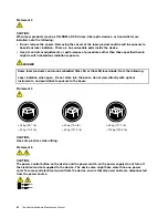
Страница 8: ...s 3A or Class 3B laser diode Note the following Laser radiation when open Do not stare into the beam do not view directly with optical instruments and avoid direct exposure to the beam Statement 4 18 kg 39 7 lb 32 kg 70 5 lb 55 kg 121 2 lb 32 kg 70 5 lb 55 kg 121 2 lb 100 kg 220 5 lb CAUTION Use safe practices when lifting Statement 5 CAUTION The power control button on the device and the power sw...

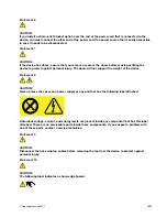
Страница 9: ...oors will not support the weight of the device Statement 8 CAUTION Never remove the cover on a power supply or any part that has the following label attached Hazardous voltage current and energy levels are present inside any component that has this label attached There are no serviceable parts inside these components If you suspect a problem with one of these parts contact a service technician Sta...

Страница 10: ...t is extended on the rails Statement 14 CAUTION Some accessory or option board outputs exceed Class 2 or limited power source limits You must install the appropriate interconnecting cabling in accordance with your local electrical code requirements Statement 15 CAUTION The power control button on the device may put the device in standby mode instead of turning off the device In addition the device...

Страница 11: ... 60 V direct current The branch circuit overcurrent protection must be rated in accordance with local electrical code requirements Use 1 3 mm2 or 16 American Wire Gauge AWG copper conductor only not exceeding 3 meters in length Torque the wiring terminal screws to 1 4 newton meters or 12 inch pounds Provide a readily available approved and rated disconnect device in the field wiring Statement 17 C...

Страница 12: ... battery is provided To avoid possible explosion do not burn the battery Replace the battery only with the Lenovo approved part Recycle or discard the battery as instructed by local regulations x ThinkServer Hardware Maintenance Manual ...

Страница 13: ...quest you will be charged for the installation Optional service CRUs Although dealing with Optional service CRUs requires some technical skills Optional service CRUs are safe for customers to replace You may install an Optional service CRU yourself or request Lenovo to install it at no additional charge under the type of warranty service that is designated for the server FRUs FRUs must be replaced...

Страница 14: ...he documents on the documentation DVD might change without notice after the first release of the DVD You can always obtain all the most up to date documentation for your server from the Lenovo Web site at http www lenovo com ThinkServerUserGuides The following documents are on the documentation DVD that comes with your server Safety Information This is a multilingual document that includes all the...

Страница 15: ...he RAID card on page 98 For information about the onboard SATA software RAID see Configuring the onboard SATA software RAID on page 74 Document for trained service personnel only The following document is intended for trained service personnel of Lenovo and is only available in English on the Lenovo Web site at http www lenovo com ThinkServerUserGuides Hardware Maintenance Manual This document pro...

Страница 16: ...4 ThinkServer Hardware Maintenance Manual ...

Страница 17: ...cable and power cord s to the server See Rear view of the server on page 19 to locate the connectors 4 Turn on the server to verify operation See Turning on the server on page 53 5 Review the Unified Extensible Firmware Interface UEFI settings and customize as needed See Using the Setup Utility program on page 55 6 Configure RAID and install the operating system and basic drivers See Using the Thi...

Страница 18: ...6 ThinkServer Hardware Maintenance Manual ...

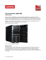
Страница 19: ...the server power cord s printed documentation documentation DVD and software media Figure 1 Server package 1 Server 2 Material box including power cord s printed documentation documentation DVD and software media Features This topic provides general information about the server features for a variety of models Depending on your specific model some features might vary or not be available For inform...

Страница 20: ...ual rank Minimum system memory 2 GB only one 2 GB memory module installed in the DIMMA2 slot Maximum system memory 16 GB one 4 GB memory module installed in each of the four memory slots For more information see System board components on page 42 and Memory module installation rules on page 90 Power supply Your server comes with one of the following power supply configurations One screw secured no...

Страница 21: ...ly is for the RDX USB drive bundle You can purchase this option directly from Lenovo The option name is Lenovo Removable Disk Technology RDX USB Drive Bundle The RDX technology combines the characteristics of tape backup with disk storage to help you protect and archive data Expansion slots The server has four expansion slots on the system board For detailed information see System board components...

Страница 22: ... server With the BMC chip no matter what condition the server operating system is in and no matter if the server is on or off as long as the server is connected to network and an ac power source the interaction with the BMC controlled servers can be achieved through system network The user can obtain the server hardware health information and system event log SEL and is able to conduct the operati...

Страница 23: ...ilable when the BMC detects the presence of an integrated keyboard video and mouse iKVM key The iKVM key is a remote management module You can purchase an iKVM key from Lenovo and install it on the iKVM key connector on the system board of your server to enable the iKVM function and activate the advanced system management features iKVM redirection The BMC firmware supports iKVM redirection over LA...

Страница 24: ...rating 10 C to 35 C 50 F to 95 F Storage 40 C to 70 C 40 F to 158 F in original shipping package Altitude 0 to 3 048 m 0 to 10 000 ft Humidity Operating 8 to 80 non condensing Storage 8 to 90 non condensing Electrical input Universal input Minimum 90 V ac Maximum 264 V ac Input frequency range 47 to 63 Hz Software This topic provides information about the software programs that you can use to help...

Страница 25: ...if you have a required RAID card installed For detailed information see Configuring RAID on page 71 PC Doctor for DOS The PC Doctor for DOS is a diagnostic tool that you can use to test and gather information about your system in order to ensure your system is working correctly and resolve any hardware issues You can download the latest version of this diagnostic program from http support lenovo c...

Страница 26: ...type model and serial number labels on the server Note Depending on the model type your server might look slightly different from the illustration in this topic Figure 2 Machine type model and serial number labels 14 ThinkServer Hardware Maintenance Manual ...

Страница 27: ... 3 Optical drive bay 1 with an optical drive installed 8 Front door handle 4 Optical drive eject close button 9 Doctor Inside Technology DIT panel available in some models 5 Optical drive status LED 1 Front panel For detailed information about the control connectors and status LEDs on the front panel see Front panel on page 17 2 Optical drive bay 2 The 5 25 inch optical drive bay 2 is for a second...

Страница 28: ...l drive status LED is blinking in green when the optical drive is working or in the POST process 6 Front door 7 Front door lock You can lock the front door to protect the hard disk drive cages from unauthorized access 8 Front door handle The front door handle helps you to open the front door 9 DIT panel The DIT panel is only available in models that come with a DIT module For more information see ...

Страница 29: ...stem status LED 2 Hard disk drive status LED 6 Front USB connector 1 3 Network Interface Controller NIC 1 status LED 7 Front USB connector 2 4 NIC 2 status LED 1 Power switch with power status LED You can press the power switch to turn on the server when you finish setting up the server You can also hold the power switch for several seconds to turn off the server if you cannot turn off the server ...

Страница 30: ...nector 2 on the rear panel of the server NIC status LED Color Description On Green The server is connected to a LAN Off None The server is disconnected from a LAN Blinking Green The LAN is connected and active 5 System status LED The system status LED helps you to determine if there are any system errors System status LED Color Description On Amber A system error has occurred Off None The server i...

Страница 31: ...e over limit LED 2 Memory module error LED 5 Power supply error LED only available on models with redundant power supply modules 3 Fan error LED 1 2 3 5 Error LEDs When one of these error LEDs is lit orange it indicates that the associated component has failed 4 Ambient temperature over limit LED When this LED is lit orange it indicates that the ambient temperature is over 38 C 100 4 F Rear view o...

Страница 32: ... Figure 6 Rear view of the server with a non hot swap power supply 1 Power cord connector 5 Expansion card area 2 Serial port 6 Ethernet connector 1 RJ 45 3 VGA DB 15 connector 7 Ethernet connector 2 RJ 45 for system management 4 Four USB connectors 8 Front door key 20 ThinkServer Hardware Maintenance Manual ...

Страница 33: ...undant power supply modules 1 Power cord connector s Used to connect the power cord s 2 Serial port Used to attach a device that uses a 9 pin serial port 3 VGA DB 15 connector Used to attach a video device such as a VGA monitor or other devices that use a VGA DB 15 connector 4 USB connectors Used to attach a device that requires a USB connector such as a USB keyboard a USB mouse a USB scanner or a...

Страница 34: ...er is disconnected from a LAN 1 Left Green Blinking The LAN is connected and active Amber On The connection speed is 1000 Mbps megabits per second Green On The connection speed is 100 Mbps 2 Right None Off The connection speed is 10 Mbps 8 Front door key Used to open or lock the front door Note Carefully save the front door key to avoid loss Server locks Locking the server cover helps prevent unau...

Страница 35: ...Padlock Your server comes with a padlock loop so that the server cover cannot be removed when a padlock is installed Figure 8 Padlock Chapter 3 Product overview 23 ...

Страница 36: ... the integrated cable lock slot at the rear of your server and is operated with a key The cable lock also locks the server cover This is the same type of lock used with many notebook computers You can order an integrated cable lock directly from Lenovo by searching for Kensington at http support lenovo com Figure 9 Integrated cable lock 24 ThinkServer Hardware Maintenance Manual ...

Страница 37: ...isk drives Figure 10 Front door lock Server components This topic provides information to help you locate the components of your server To remove the server cover and gain access to the inside of the server see Removing the server cover on page 85 The chassis configuration varies by model The following illustrations show the four main chassis configurations based on the supported hard disk drives ...

Страница 38: ...ith an optical drive installed 15 System board battery 5 Hard disk drive bay 7 16 Expansion card 6 Hard disk drive bay 6 17 Heat sink and fan assembly 7 Hard disk drive bay 5 18 System board 8 Hard disk drive bay 4 19 Rear system fan 9 Hard disk drive bay 3 20 Power supply 10 Hard disk drive bay 2 21 Four memory slots installed memory modules vary by model 11 Hard disk drive bay 1 For more informa...

Страница 39: ... bay there is a dummy hard disk drive tray to cover the place For information about the supported expansion card see System board components on page 42 Depending on the model your server might come with a screw secured non hot swap power supply or hot swap redundant power supply module s For more information about the memory modules see Memory module installation rules on page 90 Chapter 3 Product...

Страница 40: ...attery 5 Hard disk drive bay 7 15 Expansion card 6 Hard disk drive bay 6 16 Heat sink and fan assembly 7 Hard disk drive bay 5 17 System board 8 Hard disk drive bay 4 18 Rear system fan 9 Hard disk drive bay 3 19 Power supply 10 Hard disk drive bay 2 20 Four memory slots installed memory modules vary by model For more information about 1 to 4 see Front view of the server on page 15 Note The DIT mo...

Страница 41: ... with up to four 3 5 inch hot swap hard disk drives Figure 13 Components of the server with up to four 3 5 inch hot swap hard disk drives 1 DIT module available in some models 9 Front system fan 1 2 Front panel 10 System board battery 3 Optical drive bay 2 with an optical drive installed in some models 11 Expansion card varies by model 4 Optical drive bay 1 with an optical drive installed 12 Heat ...

Страница 42: ...ard disk drives varies by model For the vacant drive bay there is a dummy hard disk drive tray to cover the place For information about the supported expansion card see System board components on page 42 Depending on the model your server might come with a screw secured non hot swap power supply or hot swap redundant power supply module s For more information about the memory modules see Memory mo...

Страница 43: ...y 5 Hard disk drive bay 3 13 System board 6 Hard disk drive bay 2 14 Rear system fan 7 Hard disk drive bay 1 15 Power supply 8 Hard disk drive bay 0 16 Four memory slots installed memory modules vary by model For more information about 1 to 4 see Front view of the server on page 15 Note The DIT module 1 is only available in some models and the DIT panel also varies by model See DIT module on page ...

Страница 44: ...drive status LEDs This topic applies only to server models with hot swap hard disk drives Note Depending on the model your server might look slightly different from the illustrations in this topic Each hot swap hard disk drive has two status LEDs on the front Unlock and open the front door to gain access to the hard disk drives and view the status LEDs Figure 15 3 5 inch hot swap hard disk drive s...

Страница 45: ...een Blinking rapidly about four flashes per second amber The RAID controller is identifying the hard disk drive On green On amber The RAID array has failed and cannot recover You need to recreate a new array Blinking green Blinking slowly about one flash per second amber The hard disk drive is being rebuilt RAID card This topic provides information to help you locate the connectors on a RAID card ...

Страница 46: ... Port 0 3 RAID 5 key connector 2 Port 1 4 External connector 1 Port 0 Used to connect a mini SAS signal cable See Connecting cables on page 38 2 Port 1 Used to connect a mini SAS signal cable See Connecting cables on page 38 3 RAID 5 key connector Used to connect a ThinkServer 9240 8i RAID 5 Upgrade Key See Installing or removing the ThinkServer 9240 8i RAID 5 Upgrade Key on page 100 4 External co...

Страница 47: ...e front system fan on page 149 Notes 1 Depending on the model your server might look slightly different from the illustration in this topic 2 The following illustration is based on five to eight 3 5 inch hot swap SATA or SAS hard disk drives with two backplanes 1 Figure 18 Hot swap hard disk drive backplane locations Backplane for 3 5 inch hot swap hard disk drives This topic provides information ...

Страница 48: ...ve Figure 20 Rear view of the 3 5 inch hot swap hard disk drive backplane 1 8 pin power connector For 3 5 inch hot swap hard disk drive backplane on the lower hard disk drive cage connect the P5 power connector of the power supply to the 8 pin power connector on the backplane For 3 5 inch hot swap hard disk drive backplane on the upper hard disk drive cage connect the P4 power connector of the pow...

Страница 49: ...ap hard disk drive 5 Slot 4 for a 2 5 inch SAS hot swap hard disk drive 2 Slot 1 for a 2 5 inch SAS hot swap hard disk drive 6 Slot 5 for a 2 5 inch SAS hot swap hard disk drive 3 Slot 2 for a 2 5 inch SAS hot swap hard disk drive 7 Slot 6 for a 2 5 inch SAS hot swap hard disk drive 4 Slot 3 for a 2 5 inch SAS hot swap hard disk drive 8 Slot 7 for a 2 5 inch SAS hot swap hard disk drive Figure 22 ...

Страница 50: ... disk drives and two backplanes Server models with up to eight 2 5 inch SAS hot swap hard disk drives and one backplane Server models with up to four 3 5 inch hot swap hard disk drives and one backplane Server models with five to eight 3 5 inch hot swap hard disk drives and two backplanes For server models with five to eight SAS or SATA II 3 5 inch hot swap hard disk drives and two backplanes a re...

Страница 51: ...nnecting cables for server models with two backplanes and a RAID card For connector location information about the RAID card hot swap hard disk drive backplane and the system board refer to the related topics in Locations on page 13 For information about connecting the appropriate power connector of the power supply to the backplane see Hot swap hard disk drive backplane on page 34 Server models w...

Страница 52: ...g cables for server models with one 2 5 inch hot swap hard disk drive backplane and a RAID card For connector location information about the RAID card hot swap hard disk drive backplane and the system board refer to the related topics in Locations on page 13 For information about connecting the appropriate power connector of the power supply to the backplane see Hot swap hard disk drive backplane ...

Страница 53: ...ctor 1 P2 SATA connector 2 P3 SATA connector 3 2 If you connect the SATA hard disk drives to the system board you can configure RAID using the configuration utility for the onboard SATA software RAID See Configuring the onboard SATA software RAID on page 74 Figure 25 Mini SAS signal cable with four SATA ports and one SGPIO port The RAID card provides advanced SATA SAS RAID configurations If you ar...

Страница 54: ...ctor on the system board Figure 26 Connecting cables for server models with one 3 5 inch hot swap hard disk drive backplane and a RAID card For connector location information about the RAID card hot swap hard disk drive backplane and the system board refer to the related topics in Locations on page 13 For information about connecting the appropriate power connector of the power supply to the backp...

Страница 55: ... power connector 27 Hard disk drive LED connector 9 5 pin system fan 2 connector 28 DIT module connector 10 Microprocessor 29 Internal serial connector 11 Intel C202 chip 30 PCI card slot PCI slot 1 12 4 pin system fan 1 connector 31 PCI Express x4 card slot PCI E slot 2 13 SATA connector 1 32 BMC chip 14 SATA connector 0 33 PCI Express x8 card slot PCI E slot 3 15 SATA connector 3 34 PCI Express ...

Страница 56: ...connector of the power supply to provide main power to your server 9 5 pin system fan 2 connector Used to connect the cable of the upper front system fan front system fan 2 if your server model has two front system fans 10 Microprocessor A microprocessor incorporates most or all of the functions of a computer s central processing unit CPU on a single integrated circuit The microprocessor for your ...

Страница 57: ...ation active when you turn off the server 24 Front panel connector Used to connect the front panel cable 25 System board jumper blocks Used to configure the system board and your server See System board jumpers on page 46 26 SATA SGPIO connector Used to connect the SGPIO port of the mini SAS signal cable with four SATA ports and one SGPIO port to enable the RAID status LEDs for hot swap hard disk ...

Страница 58: ... length such as an Ethernet card or a RAID card 34 PCI Express x8 card slot PCI E slot 4 This is a PCI Express x8 lane in physical PCI 2 0 x16 slot that supports a PCI Express x8 card with 312 mm 12 28 inches in length such as a graphics card 35 Microprocessor fan connector Used to connect the heat sink and fan assembly cable 36 System fan 3 connector Used to connect the rear system fan cable 37 M...

Страница 59: ...The following illustration shows a jumper in the default setting position pin 1 and pin 2 This is the correct position for normal operation Figure 28 Default jumper setting Chapter 3 Product overview 47 ...

Страница 60: ...ot open your server or attempt any repair before reading and understanding the Safety information on page iii and Guidelines on page 83 1 Clear CMOS Recovery jumper Used to clear CMOS and recover your server to the factory default settings Note After clearing CMOS all your BIOS passwords are erased and the BIOS recovers to the factory default settings To clear CMOS do the following 1 Remove all me...

Страница 61: ...ilable in this situation 3 BIOS recovery jumper Set the jumper and boot the server from a BIOS recovery image in order to recover your BIOS settings To recover the BIOS see Recovering from a BIOS update failure on page 68 4 Clear password jumper Used to erase forgotten passwords such as an administrator password and a user password To clear passwords do the following 1 Remove all media from the dr...

Страница 62: ...e fault LED 6 POST code diagnostic LED 1 2 BMC status LED 7 POST code diagnostic LED 6 3 POST code diagnostic LED 4 8 POST code diagnostic LED 2 4 POST code diagnostic LED 0 Least Significant Bit LSB 9 POST code diagnostic LED 7 Most Significant Bit MSB 5 POST code diagnostic LED 5 10 POST code diagnostic LED 3 1 System board hardware fault LED When this LED is lit it indicates that the system boa...

Страница 63: ...0 For example if POST code diagnostic LEDs 5 6 9 and 10 are lit you can read the number as the following POST code diagnostic LED 9 7 5 3 10 8 6 4 Binary symbol 1 0 1 0 1 0 1 0 The 10101010 indicates a corresponding POST code Note The POST code diagnostic LEDs and POST error code information are intended for trained service personnel of Lenovo The following table lists information about the POST e...

Страница 64: ... 0xF9 Recovery capsule not found 11111010 0xFA Invalid recovery capsule 11010000 0xD0 Microprocessor initialization error 11010001 0xD1 North bridge initialization error 11010010 0xD2 South bridge initialization error 11010011 0xD3 Some architectural protocols not available 11010100 0xD4 PCI resource allocation error Out of resources 11010101 0xD5 No space for the legacy option ROM 11010110 0xD6 C...

Страница 65: ...he device ensure that all power cords are disconnected from the power source The server can be turned off in one of the following ways Turn off the server from the operating system if your operating system supports this feature After an orderly shutdown of the operating system the server will turn off automatically For instructions on how to shut down your specific operating system refer to the re...

Страница 66: ...2 For information about your specific operating system refer to the related documentation or help system for the operating system 54 ThinkServer Hardware Maintenance Manual ...

Страница 67: ...the correct password to enter the Setup Utility program For password information see Using passwords on page 65 Viewing information in the Setup Utility program The Setup Utility program menu lists various items about the system configuration Select a desired item to view information or change settings When working with the Setup Utility program you must use the keyboard The keys used to perform v...

Страница 68: ...t the server from a BIOS recovery image and recover the BIOS to the version in the image See System board jumpers on page 46 2 Lenovo provides the BIOS update utility on the Lenovo Support Web site You can download the BIOS image and follow the instructions on the Web site to update the BIOS See Updating or recovering the BIOS on page 67 After updating the BIOS all the BIOS settings become the def...

Страница 69: ...select a desired option by using up and down arrow keys or type desired values from the keyboard directly Some items are displayed on the menu only if the server supports the corresponding features Notes Enabled means that the function is configured Disabled means that the function is not configured Default values are in boldface in the Selections column Advanced menu items Menu item Submenu item ...

Страница 70: ...le the adjacent cache line prefetcher function Memory Configuration set memory configuration parameters and view information about the installed memory modules Memory Reset No Yes Set the memory module reset options If a memory module encounters any errors set this option to Yes to try to re initialize the memory module Intel VT d Technology Disabled Enabled Enable or disable the Intel VT d techno...

Страница 71: ...the system board SATA Port2 View the information about the SATA device connected to the SATA connector 2 on the system board SATA Port3 View the information about the SATA device connected to the SATA connector 3 on the system board SATA Port4 View the information about the SATA device connected to the SATA connector 4 on the system board SATA Configuration set SATA configuration parameters SATA P...

Страница 72: ...with no media are emulated according to the drive type Console Redirection Configuration set console redirection configuration parameters Console Redirection Disabled Serial Port 1 Serial Port 2 The setting specifies how the host computer and the remote computer which the user is using will exchange data Both computers should have the same or compatible settings Security menu This topic provides i...

Страница 73: ...d Enable or disable the TPM support To use the TPM feature you need to have a TPM module installed in the TPM connector on the system board TPM State Disabled Enabled This item is displayed when the TPM Support is set to Enabled Set the TPM State to enable or disable the TPM function The server will restart in order to change the state of TPM Server Management menu This topic provides information ...

Страница 74: ...rst boot record that it finds For example you can define a startup sequence that checks for a disc in the optical drive then checks the hard disk drive and then checks a network device For information about setting the startup sequence or selecting a startup device see Selecting a startup device on page 66 The following list showing the order in which devices will be started up is always displayed...

Страница 75: ...es depending on the available UEFI devices Specify the startup priority for all the available UEFI devices Hard Disk Drive Priority Varies depending on the available hard disk drives Specify the startup priority for all the available hard disk drives Optical Disk Drive Priority Varies depending on the available optical drives Specify the startup priority for all the available optical drives Remova...

Страница 76: ... The following table lists each item on the Exit menu with descriptions Press Enter to select the item and then select Yes when prompted to confirm the action For information about exiting the Setup Utility program see Exiting the Setup Utility program on page 67 Exit menu items Item Comments Save Changes and Exit Save your settings and exit the Setup Utility program Discard Changes and Exit Disca...

Страница 77: ...d considerations For security reasons it is recommended to use a strong password that cannot be easily compromised Notes 1 The Setup Utility program passwords are not case sensitive 2 The server supports Setup Utility program passwords that consist of up to 20 characters To set a strong password use the following guidelines Have at least eight characters in length Contain at least one alphabetic c...

Страница 78: ...o Enabled 3 When the TPM Support is set to Enabled the TPM State item is displayed Set the TPM State to Enabled 4 Press F10 to save settings and exit the Setup Utility program The server will restart in order to enable the TPM function Selecting a startup device If your server does not start up from a desired device such as the disc or hard disk drive as expected do one of the following to select ...

Страница 79: ...ion settings of your server See Using the Setup Utility program on page 55 The BMC firmware works together with an iKVM key to provide advanced server management features Your server system board has a module called electrically erasable programmable read only memory EEPROM also referred to as flash memory You can easily update the POST the BIOS and BMC firmware and the Setup Utility program by st...

Страница 80: ... default settings of the updated BIOS version You need to check and reconfigure the BIOS settings for your specific needs You can note down your specific BIOS settings before updating the BIOS for an easier reconfiguration in the new BIOS version To update flash the BIOS do the following 1 Download a BIOS update utility program and its installation instructions from the Lenovo Support Web site The...

Страница 81: ...ty program on page 55 Using the ThinkServer EasyStartup program This topic guides you to use the ThinkServer EasyStartup program to set up and configure your server The ThinkServer EasyStartup program simplifies the process of configuring RAID and installing supported Windows and Linux operating systems and device drivers on your server The program works in conjunction with your Windows or Linux o...

Страница 82: ...tical drive See Selecting a startup device on page 66 2 Wait for the program to load Then you will be prompted for the following selections The language in which you want to view the program The language of the keyboard layout you will be using with the program Note The supported languages and keyboard layouts for the ThinkServer EasyStartup program are German English Spanish French Italian Dutch ...

Страница 83: ...ed by the version of the program you are using User Guide This menu provides information about the features of the program and instructions on how to use the program Hardware list This menu displays a list of hardware devices detected by the program Configure RAID This menu guides you to configure RAID or view the current RAID configuration and make changes if needed Install operating system This ...

Страница 84: ...s good for small databases or other applications that require small capacity but complete data redundancy RAID 1 provides fault tolerance from disk errors or failures and continues to operate as long as at least one drive in the mirrored set is functioning With appropriate operating system support there can be increased read performance and only a minimal write performance reduction RAID 1 require...

Страница 85: ...ATA Software RAID 5 Key on page 102 You can install and use the MegaRAID Storage Manager program to manage the RAID array and RAID controller in an operating system environment For detailed information see Configuring the onboard SATA software RAID on page 74 Advanced SATA SAS hardware RAID configuration using the WebBIOS Configuration Utility program and RAID management using the MegaRAID Storage...

Страница 86: ...rive The installation packages for the programs are located in the Utilities and Others folder in the root directory of the DVD The ThinkServer EasyStartup DVD is designed for different types of servers and the Utilities and Others folder might contain additional installation packages that are not required to be installed into your server For more information see Installing and using the MegaRAID ...

Страница 87: ...sting array or select a boot virtual drive Initialize This menu helps you initialize virtual drive s Note Initializing a virtual drive erases all data on the virtual drive Back up any data you want to keep and ensure the operating system is not installed on the virtual drive before the initialization Objects This menu helps you configure parameters for the RAID adapter or controller the virtual dr...

Страница 88: ...re configuration For example the server needs to have the required number of SATA hard disk drives installed and connected to the system board See About RAID on page 72 for information about the required number of hard disk drives for each RAID level If you want to create a RAID 5 array using the LSI Software RAID Configuration Utility program the server also needs to have a ThinkServer SATA Softw...

Страница 89: ...tializing a virtual drive 2 Make sure that the operating system is not installed on the virtual drive you are initializing Otherwise you need to reinstall the operating system after completing the operation To initialize a virtual drive using the LSI Software RAID Configuration Utility program do the following 1 Start the LSI Software RAID Configuration Utility program See Starting the LSI Softwar...

Страница 90: ... The rebuild rate is the percentage of the computing cycles dedicated to rebuilding failing drives A rebuild rate of 100 percent means that the system gives priority to rebuilding the failing drives The rebuild rate can be configured between 0 percent and 100 percent At 0 percent the rebuild is done only if the system is not doing anything else At 100 percent the rebuild has a higher priority than...

Страница 91: ...ency check rate by typing a desired value from the keyboard directly Installing and using the MegaRAID Storage Manager program You can install and use the MegaRAID Storage Manager program to manage the RAID array and RAID controller in an operating system environment after configuring RAID The installation package for the MegaRAID Storage Manager program is on the ThinkServer EasyStartup DVD After...

Страница 92: ...e RAID refer to the MegaRAID SAS Software User Guide on the documentation DVD that comes with your server This document is also available on the Lenovo Web site at http www lenovo com ThinkServerUserGuides Configuring the Ethernet controllers The Ethernet controllers are integrated on the system board They provide an interface for connecting to a 10 Mbps 100 Mbps or 1000 Mbps network and provide f...

Страница 93: ...cate the Firmware Updater program 3 Download the ISO image for the Firmware Updater program and the installation instructions in a TXT file 4 Use any CD or DVD burning software to create a bootable disc with the ISO image 5 Print the TXT file that contains the installation instructions and follow the instructions to use the Firmware Updater program to update your system firmware Notes 1 Before dis...

Страница 94: ...82 ThinkServer Hardware Maintenance Manual ...

Страница 95: ...sues are addressed and that your server is ready to function at maximum levels of performance To download firmware updates for your server do the following 1 Go to http support lenovo com 2 Click Download Drivers Software and follow the instructions on the Web page to download firmware updates for your server See Updating the firmware on page 80 for more information Before you install optional har...

Страница 96: ... or its frame Do not touch solder joints pins or exposed circuitry Do not leave the device where others can handle and damage it Before you replace a new part touch the static protective package containing the new part to an unpainted metal part of the server for at least two seconds This reduces static electricity from the package and your body Remove the new part from the static protective packa...

Страница 97: ...rf to hang inside the server Remove jewelry such as bracelets necklaces rings and loose fitting wrist watches Remove items from your shirt pocket such as pens and pencils These items might fall into the server as you lean over it Avoid dropping any metallic objects into the server such as paper clips hairpins and screws Removing the server cover Attention Do not open your server or attempt any rep...

Страница 98: ...ch as a screwdriver to loosen the thumbscrew that secures the server cover The thumbscrew is an integrated part of the server cover and do not try to remove the thumbscrew from the server cover b It is recommended that you wait three to five minutes to let the server cool before removing the server cover Figure 32 Sliding the server cover to the rear 86 ThinkServer Hardware Maintenance Manual ...

Страница 99: ...ormation on page iii and Guidelines on page 83 This topic provides instructions on how to remove and reinstall the front bezel Before you begin print all the related instructions or ensure that you can view the PDF version on another computer for reference Note Depending on the model your server might look slightly different from the illustrations in this topic To remove and reinstall the front be...

Страница 100: ...3 Remove the front bezel by releasing the three plastic tabs on the left side and pivoting the front bezel outward Figure 34 Removing the front bezel 88 ThinkServer Hardware Maintenance Manual ...

Страница 101: ...ices If you are handling a server option refer to the appropriate installation and or removal instructions in this topic along with the instructions that come with the option Notes 1 Use only parts provided by Lenovo 2 Depending on the model your server might look slightly different from the illustrations in this topic Installing or removing a memory module This topic provides instructions on how ...

Страница 102: ...he system board 1 Memory slot 4 DIMMB2 3 Memory slot 2 DIMMA2 2 Memory slot 3 DIMMB1 4 Memory slot 1 DIMMA1 The following table provides information about the memory module installation rules that you should consider when installing or removing a memory module The X mark indicates the memory slot s into which the memory module s should be installed in different situations The numbers 1 2 3 and 4 i...

Страница 103: ...om the drives and turn off all attached devices and the server Then disconnect all power cords from electrical outlets and disconnect all cables that are connected to the server 2 Remove the server cover See Removing the server cover on page 85 3 Lay the server on its side for easier operation 4 Locate the memory slots on the system board See System board components on page 42 5 Remove any parts o...

Страница 104: ...r or attempt any repair before reading and understanding the Safety information on page iii and Guidelines on page 83 This topic provides instructions on how to remove a memory module Before you begin print all the related instructions or ensure that you can view the PDF version on another computer for reference Note To optimize system performance make sure that you consider and follow the memory ...

Страница 105: ...r drive bay filler from the drive bay or save the PCI card slot bracket in the event that you later remove the device Attention An unoccupied drive bay or PCI card slot without cover shield filler or any other protection might impact the EMI integrity and cooling of the server which might result in overheating or component damage Note The PCI cards are extremely sensitive to ESD Make sure that you...

Страница 106: ...server 5 Remove the PCI card slot bracket by removing the screw that secures the metal bracket and then lifting the bracket out of the chassis Store the PCI card slot bracket in the event that you later remove the PCI card and need the bracket to cover the place Note Carefully place the removed screw aside You will need the screw later to secure the PCI card in place Figure 40 Removing a PCI card ...

Страница 107: ... Removing a PCI card Attention Do not open your server or attempt any repair before reading and understanding the Safety information on page iii and Guidelines on page 83 This topic provides instructions on how to remove a PCI card Before you begin print all the related instructions or ensure that you can view the PDF version on another computer for reference Note Use any documentation that comes ...

Страница 108: ...place the old one or install a PCI card slot bracket to cover the place See Installing a PCI card on page 93 8 If you are instructed to return the old PCI card follow all packaging instructions and use any packaging materials that are supplied to you for shipping What to do next To work with another piece of hardware go to the appropriate section To complete the removal procedure go to Completing ...

Страница 109: ...What to do next To work with another piece of hardware go to the appropriate section To complete the installation go to Completing the parts replacement on page 168 Then continue with the following procedure to install the Ethernet card driver if you are using a Windows operating system On Linux operating systems you do not need to install any device driver for the Ethernet card On Windows operati...

Страница 110: ...ure go to Completing the parts replacement on page 168 Installing or removing the RAID card This topic provides instructions on how to install or remove the RAID card A specific RAID card is required for server models with more than four hard disk drives or models that use SAS hard disk drives You can also install the RAID card for advanced SATA SAS hardware RAID functions For more information see...

Страница 111: ...the operating system after removing the RAID card If you remove the RAID card you will lose the advanced SATA SAS hardware RAID functions Also a specific RAID card is required for server models with more than four hard disk drives or models that use SAS hard disk drives Before you begin print all the related instructions or ensure that you can view the PDF version on another computer for reference...

Страница 112: ...air before reading and understanding the Safety information on page iii and Guidelines on page 83 This topic provides instructions on how to install the RAID 5 key on the RAID card Note This topic applies only to models that have a RAID card installed Before you begin print all the related instructions or ensure that you can view the PDF version on another computer for reference Note Use any docum...

Страница 113: ...ard Attention Do not open your server or attempt any repair before reading and understanding the Safety information on page iii and Guidelines on page 83 This topic provides instructions on how to remove the RAID 5 key from the RAID card Notes 1 This topic applies only to server models that have a RAID card with the RAID 5 key option installed 2 If you remove the RAID 5 key from the RAID card the ...

Страница 114: ...procedure go to Completing the parts replacement on page 168 As the hardware RAID 5 and 50 levels are not available without the RAID 5 key you might need to reconfigure RAID for your server Refer to the MegaRAID SAS Software User Guide on the documentation DVD that comes with your server for information about how to configure the hardware RAID Installing or removing the ThinkServer SATA Software R...

Страница 115: ...de for easier operation 4 Touch the static protective package that contains the system board RAID 5 key to any unpainted surface on the outside of the server Then take the system board RAID 5 key out of the package 5 Locate the iButton socket on the system board Insert one side of the system board RAID 5 key under one of the retaining clips on the iButton socket Then carefully press the other side...

Страница 116: ... key option installed 2 If you remove the system board RAID 5 key the onboard SATA software RAID 5 will be disabled Before you begin print all the related instructions or ensure that you can view the PDF version on another computer for reference Note Use any documentation that comes with the system board RAID 5 key and follow those instructions in addition to the instructions in this topic To remo...

Страница 117: ...procedure go to Completing the parts replacement on page 168 As the onboard SATA software RAID 5 is not available without the system board RAID 5 key you might need to reconfigure RAID for your server See Configuring RAID on page 71 Installing or removing the ThinkServer iKVM Remote Management Module This topic provides instructions on how to install or remove the ThinkServer iKVM Remote Managemen...

Страница 118: ...or reference Note Use any documentation that comes with the iKVM key and follow those instructions in addition to the instructions in this topic To install the iKVM key do the following 1 Remove all media from the drives and turn off all attached devices and the server Then disconnect all power cords from electrical outlets and disconnect all cables that are connected to the server 2 Remove the se...

Страница 119: ...te Management Module User Guide on the documentation DVD that comes with your server for more information about the iKVM function and server remote management Removing the iKVM key Attention Do not open your server or attempt any repair before reading and understanding the Safety information on page iii and Guidelines on page 83 This topic provides instructions on how to remove the iKVM key if the...

Страница 120: ...to the server 2 Remove the server cover See Removing the server cover on page 85 3 Lay the server on its side for easier operation 4 Locate the iKVM key on the system board and then lift the iKVM key straight up to remove it from the iKVM key connector Figure 48 Removing the iKVM key 5 If you are instructed to return the old iKVM key follow all packaging instructions and use any packaging material...

Страница 121: ...uctions or ensure that you can view the PDF version on another computer for reference Note Use any documentation that comes with the TPM module and follow those instructions in addition to the instructions in this topic To install the TPM module do the following 1 Remove all media from the drives and turn off all attached devices and the server Then disconnect all power cords from electrical outle...

Страница 122: ...n on page iii and Guidelines on page 83 This topic provides instructions on how to remove the TPM module if the server has one installed Before you begin print all the related instructions or ensure that you can view the PDF version on another computer for reference Notes 1 Use any documentation that comes with the TPM module and follow those instructions in addition to the instructions in this to...

Страница 123: ...ls that are supplied to you for shipping What to do next To work with another piece of hardware go to the appropriate section To complete the removal procedure go to Completing the parts replacement on page 168 Installing or removing the DIT module This topic provides instructions on how to install or remove the DIT module The DIT module which is only available in some models provides diagnostic L...

Страница 124: ...onnect all cables that are connected to the server 2 Remove the server cover See Removing the server cover on page 85 3 Remove the front bezel See Removing and reinstalling the front bezel on page 87 4 Touch the static protective package that contains the DIT module to any unpainted surface on the outside of the server Then take the DIT module out of the package 5 Connect the signal cable to the r...

Страница 125: ... Completing the parts replacement on page 168 Removing the DIT module Attention Do not open your server or attempt any repair before reading and understanding the Safety information on page iii and Guidelines on page 83 This topic provides instructions on how to remove the DIT module This topic applies only to server models that come with the DIT module Before you begin print all the related instr...

Страница 126: ... the cable routing and then release the signal cable of the DIT module from any cable clips or ties in the chassis 8 Remove the screw 1 on the chassis that secures the DIT module Then carefully remove the DIT module from the chassis and pull the signal cable of the DIT module out of the hole in the chassis Figure 53 Removing the DIT module 9 Disconnect the signal cable from the rear of the DIT mod...

Страница 127: ...roduct could result in exposure to hazardous laser radiation There are no serviceable parts inside the device Use of controls or adjustments or performance of procedures other than those specified herein might result in hazardous radiation exposure DANGER Some laser products contain an embedded Class 3A or Class 3B laser diode Note the following Laser radiation when open Do not stare into the beam...

Страница 128: ...e drives and turn off all attached devices and the server Then disconnect all power cords from electrical outlets and disconnect all cables that are connected to the server 2 Remove the server cover See Removing the server cover on page 85 3 Locate the optical drive bays See Server components on page 25 4 Depending on whether you are installing or replacing an optical drive do one of the following...

Страница 129: ...it is projected from the front of the chassis Then hold the optical drive from the front and completely slide it out of the chassis Figure 55 Removing the optical drive 5 Touch the static protective package that contains the new optical drive to any unpainted surface on the outside of the server Then take the new optical drive and the signal cable out of the package Chapter 6 Installing removing o...

Страница 130: ...only the situation in which the front bezel has not been removed Figure 56 Installing the optical drive 7 Connect the appropriate power cable 1 and the signal cable 2 to the rear of the new optical drive Figure 57 Connecting cables to the rear of the optical drive 8 If necessary connect the other end of the signal cable to the appropriate SATA connector on the system board See System board compone...

Страница 131: ...ending on the server model The vacant bays are either covered by an EMI protective panel or occupied by dummy hard disk drive trays When you install a hot swap hard disk drive save the removed dummy hard disk drive tray from the drive bay in the event that you later remove the hot swap hard disk drive and need the dummy tray to cover the place Attention An unoccupied drive bay without any other pr...

Страница 132: ... or replace a hot swap hard disk drive do the following 1 Use the front door key to unlock the front door and then use the front door handle 1 to pivot the front door to the open position Figure 58 Opening the front door of the server 2 Locate the appropriate hard disk drive bay See Server components on page 25 120 ThinkServer Hardware Maintenance Manual ...

Страница 133: ...ease button 1 to open the handle of the hot swap hard disk drive or the dummy tray Figure 59 Opening the handle of the hot swap hard disk drive or the dummy tray Chapter 6 Installing removing or replacing hardware 121 ...

Страница 134: ...t swap hard disk drive or the dummy tray 5 Touch the static protective package that contains the new hot swap hard disk drive to any unpainted surface on the outside of the server Then take the new hot swap hard disk drive out of the package Note Do not touch the circuit board on the hard disk drive 122 ThinkServer Hardware Maintenance Manual ...

Страница 135: ...disk drive dummy tray in the event that you later remove the hot swap hard disk drive and need a dummy tray to cover the drive bay If you are replacing a hot swap hard disk drive and are instructed to return the old hot swap hard disk drive follow all packaging instructions and use any packaging materials that are supplied to you for shipping What to do next To work with another piece of hardware ...

Страница 136: ...hard disk drive bays in your server For RAID configuration the hard disk drives must be the same type with the same capacity if they are within a single RAID array For more information see Configuring RAID on page 71 For hard disk drives with different capacities install the hard disk drive with the lowest capacity first Before you begin print all the related instructions or ensure that you can vi...

Страница 137: ...door key to unlock the front door and then use the front door handle 1 to pivot the front door to the open position Figure 62 Opening the front door of the server Chapter 6 Installing removing or replacing hardware 125 ...

Страница 138: ... the non hot swap hard disk drive s CPU MEM PSU CPU MEM PSU 1 2 Figure 63 Removing the EMI protective panel 4 Remove the server cover See Removing the server cover on page 85 5 Remove the front system fan 1 See Replacing the front system fan on page 149 6 Locate the appropriate non hot swap hard disk drive See Server components on page 25 Then disconnect the SATA signal cable and the power cable f...

Страница 139: ...MEM PSU CPU MEM PSU 1 2 Figure 64 Sliding the non hot swap hard disk drive out of the bay 8 Flex the sides of the blue bracket to remove the non hot swap hard disk drive from the bracket Save the bracket for future use Note Do not touch the circuit board on the hard disk drive 9 Reinstall the front system fan 1 See Replacing the front system fan on page 149 Chapter 6 Installing removing or replaci...

Страница 140: ... go to Completing the parts replacement on page 168 Then you might need to reconfigure RAID for your server See Configuring RAID on page 71 Installing a non hot swap hard disk drive Attention Do not open your server or attempt any repair before reading and understanding the Safety information on page iii and Guidelines on page 83 This topic provides instructions on how to install a non hot swap ha...

Страница 141: ...e hard disk drive and follow those instructions in addition to the instructions in this topic To install a non hot swap hard disk drive do the following 1 Remove all media from the drives and turn off all attached devices and the server Then disconnect all power cords from electrical outlets and disconnect all cables that are connected to the server 2 Use the front door key to unlock the front doo...

Страница 142: ...protective panel 4 Remove the server cover See Removing the server cover on page 85 5 Remove the front system fan 1 See Replacing the front system fan on page 149 6 Locate the appropriate non hot swap hard disk drive bay See Server components on page 25 7 Touch the static protective package that contains the new non hot swap hard disk drive to any unpainted surface on the outside of the server The...

Страница 143: ... in the hard disk drive so that the hard disk drive can be seated in the bracket Note Do not touch the circuit board 3 on the bottom of the hard disk drive Figure 68 Installing the non hot swap hard disk drive into the bracket 9 Slide the new non hot swap hard disk drive with bracket into the drive bay until it snaps into position Chapter 6 Installing removing or replacing hardware 131 ...

Страница 144: ...cation information about the hard disk drive bays and SATA connectors on the system board Non hot swap hard disk drive Power connector System board SATA connector Installed in bay 0 P9 power connector SATA connector 0 Installed in bay 1 P10 power connector SATA connector 1 Installed in bay 2 P7 power connector SATA connector 2 Installed in bay 3 P8 power connector SATA connector 3 11 Connect the o...

Страница 145: ...ing and understanding the Safety information on page iii and Guidelines on page 83 This topic provides instructions on how to replace the hot swap hard disk drive backplane This topic applies only to server models that have hot swap hard disk drive s installed Before you begin print all the related instructions or ensure that you can view the PDF version on another computer for reference Note Depe...

Страница 146: ...acing a hot swap hard disk drive on page 119 7 Note down the cable connections on the backplane and then disconnect all the cables from the backplane 8 Lift the release latch 1 and slide the hard disk drive cage out of the front of the chassis Note The following illustration shows the 3 5 inch hard disk drive cage For the 2 5 inch hard disk drive cage the removal procedure is the same Figure 71 Re...

Страница 147: ...e package that contains the new hot swap hard disk drive backplane to any unpainted surface on the outside of the server Then remove the new backplane from the package Note Carefully handle the backplane by its edges 11 Position the new backplane on the hard disk drive cage so that the screw holes in the new backplane are aligned with the corresponding holes in the hard disk drive cage Then do one...

Страница 148: ... 5 inch hard disk drive cage the installation procedure is the same Figure 76 Installing the hard disk drive cage 13 Reinstall all the hot swap hard disk drives and dummy trays if any in the hard disk drive cage See Installing or replacing a hot swap hard disk drive on page 119 14 Refer to your note and reconnect the cables to the backplane 15 Reinstall the front system fan See Replacing the front...

Страница 149: ...ly or any part that has the following label attached Hazardous voltage current and energy levels are present inside any component that has this label attached There are no serviceable parts inside these components If you suspect a problem with one of these parts contact a service technician Before you begin print all the related instructions or ensure that you can view the PDF version on another c...

Страница 150: ...the hot swap hard disk drive backplane s 6 Release the power supply assembly cables from the cable clips and ties in the chassis 7 Remove the four screws 1 at the rear of the chassis that secure the power supply assembly Then push the power supply assembly from the rear until it is released from the metal retaining tab 2 CPU MEM Figure 77 Releasing the non hot swap power supply assembly 138 ThinkS...

Страница 151: ...tic protective package that contains the new power supply assembly to any unpainted surface on the outside of the server Then remove the new power supply assembly from the package and ensure that the new power supply assembly is the correct replacement See Features on page 7 for information about the supported power supply assemblies Chapter 6 Installing removing or replacing hardware 139 ...

Страница 152: ...properly route the cables and secure the cables with the cable clips and ties in the chassis 12 Reinstall the front system fan s See Replacing the front system fan on page 149 13 If you are instructed to return the old non hot swap power supply assembly follow all packaging instructions and use any packaging materials that are supplied to you for shipping What to do next To work with another piece...

Страница 153: ...supply module as soon as you remove the failing one or cover the other bay with a shield if you just use one module to provide power CAUTION Hazardous moving parts Keep fingers and other body parts away CAUTION Never remove the cover on a power supply or any part that has the following label attached Hazardous voltage current and energy levels are present inside any component that has this label a...

Страница 154: ...can first carefully slide the redundant power supply module a little bit out to release it from the secured position Then completely slide it out of the chassis Figure 80 Removing a hot swap redundant power supply module 2 Touch the static protective package that contains the new hot swap redundant power supply module to any unpainted surface on the outside of the server Then remove the new hot sw...

Страница 155: ... supply module 4 If you are instructed to return the old hot swap redundant power supply module follow all packaging instructions and use any packaging materials that are supplied to you for shipping 5 To work with another piece of hardware go to the appropriate section Replacing the power distribution board and cage assembly Attention Do not open your server or attempt any repair before reading a...

Страница 156: ...e hot swap redundant power supply module s See Replacing a hot swap redundant power supply module on page 140 Note If your server comes with one hot swap redundant power supply module installed in the redundant power supply module bay 1 the bay number is marked on the rear of the chassis there is a shied installed on bay 2 to protect the empty bay Remove the shield and save it for future use 3 Rem...

Страница 157: ...leased from the metal retaining tab 3 and then carefully lift it out of the chassis Figure 82 Removing the power distribution board and cage assembly 9 Touch the static protective package that contains the new power distribution board and cage assembly to any unpainted surface on the outside of the server Then remove the new power distribution board and cage assembly from the package Chapter 6 Ins...

Страница 158: ...of the new power distribution board and cage assembly to the system board all drives and or hot swap hard disk drive backplane s depending on the model Then properly route the cables and secure the cables with the cable clips and ties in the chassis 12 Reinstall the front system fan s See Replacing the front system fan on page 149 13 Reinstall the hot swap redundant power supply module s and or th...

Страница 159: ...ctrical outlets and disconnect all cables that are connected to the server 2 Remove the server cover See Removing the server cover on page 85 3 Remove the front bezel See Removing and reinstalling the front bezel on page 87 4 Locate the front panel See Front panel on page 17 5 Remove the front system fan s See Replacing the front system fan on page 149 6 Disconnect the signal cables of the front p...

Страница 160: ...oving the front panel board assembly 9 Touch the static protective package that contains the new front panel board assembly to any unpainted surface on the outside of the server Then take the new front panel board assembly out of the package 10 Note the cable connection Then disconnect the signal cables from the rear of the old front panel board assembly and connect them to the rear of the new one...

Страница 161: ...ur note You might need to secure the signal cables with cable clips or ties in the chassis 14 Reinstall the front system fan s See Replacing the front system fan on page 149 15 Reinstall the front bezel See Removing and reinstalling the front bezel on page 87 16 If you are instructed to return the old front panel board assembly follow all packaging instructions and use any packaging materials that...

Страница 162: ...ted instructions or ensure that you can view the PDF version on another computer for reference Note Depending on the model your server might look slightly different from the illustrations in this topic To replace the front system fan do the following 1 Remove all media from the drives and turn off all attached devices and the server Then disconnect all power cords from electrical outlets and disco...

Страница 163: ...move the new front system fan from the package 7 Position the new front system fan on the system fan 1 mounting area of the chassis so that the three tips 1 on the bottom of the front system fan are aligned with the corresponding holes in the mounting area Meanwhile make sure that the two posts 2 of the front system fan are aligned with the corresponding holes in the inner side of the chassis Then...

Страница 164: ...o not open your server or attempt any repair before reading and understanding the Safety information on page iii and Guidelines on page 83 This topic provides instructions on how to replace the rear system fan CAUTION Hazardous moving parts Keep fingers and other body parts away Before you begin print all the related instructions or ensure that you can view the PDF version on another computer for ...

Страница 165: ...and pulling the rear system fan out of the chassis Figure 88 Removing the rear system fan 6 Touch the static protective package that contains the new rear system fan to any unpainted surface on the outside of the server Then remove the new rear system fan from the package Chapter 6 Installing removing or replacing hardware 153 ...

Страница 166: ...d See System board components on page 42 9 If you are instructed to return the old rear system fan follow all packaging instructions and use any packaging materials that are supplied to you for shipping What to do next To work with another piece of hardware go to the appropriate section To complete the replacement go to Completing the parts replacement on page 168 Replacing the heat sink and fan a...

Страница 167: ...tached devices and the server Then disconnect all power cords from electrical outlets and disconnect all cables that are connected to the server 2 Remove the server cover See Removing the server cover on page 85 3 Locate the heat sink and fan assembly See Server components on page 25 4 Lay the server on its side for easier operation If necessary remove any installed PCI card that might impede your...

Страница 168: ...t from the microprocessor and then lift the heat sink and fan assembly off the system board 8 Lay aside the old heat sink and fan assembly Touch the static protective package that contains the new heat sink and fan assembly to any unpainted surface on the outside of the server Then remove the new heat sink and fan assembly from the package Note When handling the heat sink and fan assembly do not t...

Страница 169: ...croprocessor fan connector on the system board See System board components on page 42 Note If the heat sink and fan assembly cable is too long loosely knot the cable for proper cable routing 12 If you are instructed to return the old heat sink and fan assembly follow all packaging instructions and use any packaging materials that are supplied to you for shipping What to do next To work with anothe...

Страница 170: ...nnect all cables that are connected to the server 2 Remove the server cover See Removing the server cover on page 85 3 Lay the server on its side for easier operation 4 Remove the heat sink and fan assembly See Replacing the heat sink and fan assembly on page 154 5 Gently press down the small handle on the microprocessor socket and then pull the handle a little bit outward to release it from the s...

Страница 171: ...o the microprocessor socket while it is exposed The socket pins must be kept as clean as possible 8 Touch the static protective package that contains the new microprocessor to any unpainted surface on the outside of the server Then remove the new microprocessor from the package 9 Remove the new microprocessor from the protective cover that protects the gold contacts on the bottom of the new microp...

Страница 172: ...or 11 Close the microprocessor retainer Gently press down the small handle and then push the handle inward to lock the retainer into position and secure the new microprocessor in the socket Figure 96 Securing the microprocessor in the socket 12 Reinstall the heat sink and fan assembly See Replacing the heat sink and fan assembly on page 154 13 If you are instructed to return the old microprocessor...

Страница 173: ...e than 100 C 212 F Repair or disassemble Dispose of the battery as required by local ordinances or regulations The following statement applies to users in the state of California U S A California Perchlorate Information Products containing CR manganese dioxide lithium coin cell batteries may contain perchlorate Perchlorate Material special handling may apply See http www dtsc ca gov hazardouswaste...

Страница 174: ... section To complete the replacement go to Completing the parts replacement on page 168 After you replace the system board battery you must reset passwords reset system date and time and reconfigure the server See Chapter 5 Configuring the server on page 55 Replacing the system board Attention Do not open your server or attempt any repair before reading and understanding the Safety information on ...

Страница 175: ...t locations cable connections and cable routing in the server 5 Remove all memory modules and PCI cards including the RAID card and Ethernet card that are currently installed See Removing a memory module on page 92 and Removing a PCI card on page 95 6 Remove the heat sink and fan assembly See Replacing the heat sink and fan assembly on page 154 7 Remove the TPM module if one is installed See Remov...

Страница 176: ...umerical sequence as shown Then carefully remove the system board out of the chassis Figure 99 Removing the screws that secure the system board 13 Place both the old system board and the new system board on a clean flat and ESD safe surface 164 ThinkServer Hardware Maintenance Manual ...

Страница 177: ...r socket while it is exposed The socket pins must be kept as clean as possible Figure 100 Removing the microprocessor socket cover 15 Remove the microprocessor from the old system board and install it directly on the new system board See Replacing the microprocessor on page 157 16 The old system board must be returned with a microprocessor socket cover to protect the pins on the socket during ship...

Страница 178: ...ne corner of the microprocessor socket cover is the orientation indicator The microprocessor socket cover is in the correct orientation when this indicator faces toward the beveled corner 4 of the microprocessor socket Figure 101 Installing the microprocessor socket cover c Make sure that the microprocessor socket cover is properly seated and then gently press it down until it is securely seated i...

Страница 179: ...d are aligned with those in the chassis Then install the eight screws following the numerical sequence as shown to secure the new system board in the chassis Figure 104 Installing the screws to secure the system board 18 Install all parts and connect all cables that you removed from the old system board to the new system board Refer to the information that you have noted down and the related topic...

Страница 180: ...ention For proper cooling and airflow reinstall the server cover before turning on the server Operating the server for extended periods of time more than 30 minutes with the server cover removed might damage server components Before you begin print all the related instructions or ensure that you can view the PDF version on another computer for reference Note Depending on the model your server migh...

Страница 181: ...h the corresponding holes in the top edge of the chassis Pivot the server cover to close it Figure 105 Closing the server cover 5 Slide the server cover to the front of the chassis until it snaps into position Figure 106 Installing the server cover 6 Tighten the thumbscrew on the server cover to secure the server cover in place Chapter 6 Installing removing or replacing hardware 169 ...

Страница 182: ...for the first time after you install remove or replace a device you might need to update the server configuration Some optional devices have device drivers that you must install For information about installing device drivers use the documentation that comes with each optional device To obtain the supported device drivers for your server from the Lenovo Support Web site go to http support lenovo c...

Страница 183: ...solved 6 View the SEL to diagnose problems See Viewing the system event log on page 172 7 Turn on the server and press Esc as soon as you see the logo screen to view any diagnostic messages 8 Download and use the PC Doctor for DOS diagnostic program to diagnose problems See Using the diagnostic program on page 172 9 Refer to Basic troubleshooting tables on page 172 and follow the instructions for ...

Страница 184: ...ical drive when you complete the diagnostic process Viewing the system event log The system event log SEL contains information about all the POST and system management interrupt SMI events You can view the SEL to diagnose system problems The BMC implements the SEL as specified in the IPMI 2 0 specification The SEL is accessible regardless of the system power state through the BMC in band and out o...

Страница 185: ...em is solved If none of these actions solve the problem see Troubleshooting procedure on page 171 for the subsequent steps you should check after using the information in this topic If the problem cannot be solved by yourself seek technical assistance See Chapter 9 Getting information help and service on page 213 Notes 1 If you are instructed to remove install or replace any CRUs refer to the rela...

Страница 186: ...ation in this topic If the problem cannot be solved by yourself seek technical assistance See Chapter 9 Getting information help and service on page 213 Notes 1 If you are instructed to remove install or replace any CRUs refer to the related procedure in Chapter 6 Installing removing or replacing hardware on page 83 2 If the server model comes with hot swap hard disk drives the status LEDs on each...

Страница 187: ... b Replace the affected backplane Multiple hard disk drives fail 1 Run any diagnostic programs to test the hard disk drives 2 Make sure that the cable connection is correct See Connecting cables on page 38 3 Reconnect the power cable 4 Reconnect the signal cable 5 Replace the affected signal cable 6 For hot swap hard disk drives if you suspect a problem with the backplane replace the affected back...

Страница 188: ...correct type supported by the server See Features on page 7 You follow the memory module installation rules See Memory module installation rules on page 90 All memory modules are seated correctly and securely The system firmware is up to date 2 Run any diagnostic programs to test the memory modules 3 Reinstall the memory modules 4 Replace the suspect memory modules 5 Trained service technician onl...

Страница 189: ...B hub disconnect the device from the hub and connect it directly to the server The device drivers are installed correctly The USB controller is enabled in the Setup Utility program See Using the Setup Utility program on page 55 2 Restart the server 3 Replace the USB device POST error codes Each time you turn on the system it performs a series of tests that checks the operation of the system and op...

Страница 190: ...178 ThinkServer Hardware Maintenance Manual ...

Страница 191: ...part is an Optional service CRU Note The server configuration varies by model The following illustration shows only one type of server configuration server models with up to four 3 5 inch hot swap hard disk drives to provide a general view of the component locations For more information about the major server configurations see Server components on page 25 Figure 107 Component locations Major FRUs...

Страница 192: ...ll models MT 0441 CTO all models 03X3573 2 3 Optical drive DVD ROM drive 16x 48x SATA MT 0387 CTO 11U 11G 12U 12G MT 0388 CTO 11U 12U 12G 13U 13G 14U MT 0389 CTO 11U MT 0390 CTO MT 0391 CTO 11U MT 0392 CTO 11U 12U 13U 14U 15U MT 0393 CTO MT 0441 CTO 71Y5543 1 3 Optical drive DVD Burner CD RW Rambo 8 SATA MT 0387 CTO MT 0388 CTO MT 0389 CTO MT 0390 CTO 11U 11G 12U 12G 13U 13G MT 0391 CTO MT 0392 CT...

Страница 193: ... MT 0388 CTO MT 0389 CTO MT 0390 CTO MT 0391 CTO MT 0392 CTO MT 0393 CTO MT 0441 CTO 67Y1421 1 3 Lenovo 320 GB RDX USB drive bundle cartridge MT 0387 CTO MT 0388 CTO MT 0389 CTO MT 0390 CTO MT 0391 CTO MT 0392 CTO MT 0393 CTO MT 0441 CTO 67Y1422 1 3 Lenovo 500 GB RDX USB drive bundle cartridge MT 0387 CTO MT 0388 CTO MT 0389 CTO MT 0390 CTO MT 0391 CTO MT 0392 CTO MT 0393 CTO MT 0441 CTO 67Y1423 1...

Страница 194: ...T 0388 CTO MT 0389 CTO MT 0390 CTO MT 0391 CTO MT 0392 CTO MT 0393 CTO MT 0441 CTO 03X3910 1 4 Hard disk drive hot swap 1 TB SATA enterprise 7200 rpm 3 Gb s 3 5 inch drive assembly MT 0387 CTO MT 0388 CTO MT 0389 CTO MT 0390 CTO MT 0391 CTO MT 0392 CTO MT 0393 CTO MT 0441 CTO 03X3911 1 4 Hard disk drive hot swap 2 TB SATA enterprise 7200 rpm 3 Gb s 3 5 inch drive assembly MT 0387 CTO MT 0388 CTO M...

Страница 195: ...0387 CTO MT 0388 CTO MT 0389 CTO MT 0390 CTO MT 0391 CTO MT 0392 CTO MT 0393 CTO MT 0441 CTO 03X3913 1 4 Hard disk drive non hot swap 1 TB SATA enterprise 7200 rpm 3 Gb s 3 5 inch drive assembly MT 0387 CTO MT 0388 CTO MT 0389 CTO MT 0390 CTO MT 0391 CTO MT 0392 CTO MT 0393 CTO MT 0441 CTO 03X3914 1 4 Hard disk drive non hot swap 2 TB SATA enterprise 7200 rpm 3 Gb s 3 5 inch drive assembly MT 0387...

Страница 196: ...0388 CTO MT 0389 CTO MT 0390 CTO MT 0391 CTO MT 0392 CTO MT 0393 CTO MT 0441 CTO 03X3917 1 4 Hard disk drive hot swap 600 GB SAS enterprise 6 Gb s xx MB cache 3 5 inch drive assembly MT 0387 CTO MT 0388 CTO MT 0389 CTO MT 0390 CTO MT 0391 CTO MT 0392 CTO MT 0393 CTO MT 0441 CTO 03X3918 1 4 Hard disk drive hot swap 300 GB SAS enterprise 6 Gb s xx MB cache 2 5 inch drive assembly MT 0387 CTO MT 0388...

Страница 197: ... MT 0393 CTO MT 0441 CTO 03X3921 1 5 Front system fan second cage 9225 fan MT 0387 CTO all models MT 0388 CTO all models MT 0389 CTO all models MT 0390 CTO all models MT 0391 CTO all models MT 0392 CTO all models MT 0393 CTO all models MT 0441 CTO all models 03X3707 1 6 System board CMOS battery MT 0387 CTO 11U 11G 12U 12G MT 0388 CTO 11U 12U 12G 13U 13G 14U MT 0389 CTO 11U 11F MT 0390 CTO 11U 11G...

Страница 198: ...TO MT 0392 CTO MT 0393 CTO MT 0441 CTO 03X3624 2 8 Microprocessor Xeon quad core E31220 8 MB 3 1 GHz 80 W MT 0387 CTO MT 0388 CTO MT 0389 CTO MT 0390 CTO 11U 11G 12U 12G MT 0391 CTO MT 0392 CTO MT 0393 CTO 12U 12G MT 0441 CTO 11U 11G 03X3625 2 8 Microprocessor Xeon quad core E31230 8 MB 3 2 GHz 80 W MT 0387 CTO MT 0388 CTO MT 0389 CTO MT 0390 CTO MT 0391 CTO MT 0392 CTO MT 0393 CTO MT 0441 CTO 14U...

Страница 199: ... CTO MT 0392 CTO MT 0393 CTO MT 0441 CTO 15U 15G 03X3628 2 8 Microprocessor Core i3 2100 3 1 GHz dual core 3 M 65 W 1 GT 1333 MT 0387 CTO 11U 11G 12U 12G MT 0388 CTO 11U 12U 12G 13U 13G 14U MT 0389 CTO 11U MT 0390 CTO 13U 13G MT 0391 CTO 11U MT 0392 CTO 11U 12U 13U 14U 15U MT 0393 CTO 11U 11G MT 0441 CTO 13U 13G 03T8011 2 8 Microprocessor Core i3 2120 3 3 GHz dual core 3 M 65 W 1 GT 1333 MT 0387 C...

Страница 200: ... MT 0390 CTO all models MT 0391 CTO all models MT 0392 CTO all models MT 0393 CTO all models MT 0441 CTO all models 46U3197 1 10 System fan assembly MT 0387 CTO all models MT 0388 CTO all models MT 0389 CTO all models MT 0390 CTO all models MT 0391 CTO all models MT 0392 CTO all models MT 0393 CTO all models MT 0441 CTO all models 03X3948 1 11 Power supply GPS 400CB B 400 W ATX power supply REV 00...

Страница 201: ... 12U 12G MT 0441 CTO 11U 11G 12U 12G 13U 13G 14U 14G 15U 15G 16U 16G 03X3801 1 12 Memory module 2 GB 1RX8 PC3 10600E ECC UDIMM DDR3 1333 2 Gbit MT 0387 CTO 11U 11G 12U 12G MT 0388 CTO 11U 12U 12G 13U 13G 14U MT 0389 CTO 11U MT 0390 CTO 11U 11G 12U 12G 13U 13G MT 0391 CTO 11U MT 0392 CTO 11U 12U 13U 14U 15U MT 0393 CTO 11U 11G MT 0441 CTO 13U 13G 03X3660 1 12 Memory module 4 GB 2RX8 PC3 10600E ECC ...

Страница 202: ...91 CTO all models MT 0392 CTO all models MT 0393 CTO all models MT 0441 CTO all models 03X3842 2 2 5 inch hard disk drive tray V2 0 MT 0387 CTO all models MT 0388 CTO all models MT 0389 CTO all models MT 0390 CTO all models MT 0391 CTO all models MT 0392 CTO all models MT 0393 CTO all models MT 0441 CTO all models 03X3836 2 3 5 inch hard disk drive dummy tray V2 0 MT 0387 CTO all models MT 0388 CT...

Страница 203: ...0391 CTO all models MT 0392 CTO all models MT 0393 CTO all models MT 0441 CTO all models 03X3703 2 2 5 inch hard disk drive cage MT 0387 CTO all models MT 0388 CTO all models MT 0389 CTO all models MT 0390 CTO all models MT 0391 CTO all models MT 0392 CTO all models MT 0393 CTO all models MT 0441 CTO all models 03X3704 2 Non hot swap hard disk drive cage shield MT 0387 CTO all models MT 0388 CTO a...

Страница 204: ...CTO all models MT 0392 CTO all models MT 0393 CTO all models MT 0441 CTO all models 03X5999 2 Hot swap 2 5 x 8 SAS SATA backplane MT 0387 CTO all models MT 0388 CTO all models MT 0389 CTO all models MT 0390 CTO all models MT 0391 CTO all models MT 0392 CTO all models MT 0393 CTO all models MT 0441 CTO all models 03X6000 2 KT2A bezel assembly with label MT 0387 CTO all models MT 0388 CTO all models...

Страница 205: ...TO all models MT 0441 CTO all models 03X3714 2 KT2A 9225 38 fan holder MT 0387 CTO all models MT 0388 CTO all models MT 0389 CTO all models MT 0390 CTO all models MT 0391 CTO all models MT 0392 CTO all models MT 0393 CTO all models MT 0441 CTO all models 03X3717 2 450 mm 17 72 inches single to mini SAS cable 4 1 with one SGPIO port mini SAS signal cable with four SATA ports and one SGPIO port MT 0...

Страница 206: ...l models MT 0390 CTO all models MT 0391 CTO all models MT 0392 CTO all models MT 0393 CTO all models MT 0441 CTO all models 03X3696 1 Lenovo RDX USB drive bundle cables MT 0387 CTO MT 0388 CTO MT 0389 CTO MT 0390 CTO MT 0391 CTO MT 0392 CTO MT 0393 CTO MT 0441 CTO 67Y1425 1 Adapters and miscellaneous FRUs The following table lists information about adapters and miscellaneous FRUs FRU FRU number CR...

Страница 207: ...240 8i RAID 5 Upgrade Key MT 0387 CTO MT 0388 CTO MT 0389 CTO MT 0390 CTO MT 0391 CTO MT 0392 CTO MT 0393 CTO MT 0441 CTO 03X3604 1 Remote Management Module V1 0 MT 0387 CTO MT 0388 CTO MT 0389 CTO MT 0390 CTO MT 0391 CTO MT 0392 CTO MT 0393 CTO MT 0441 CTO 03X3666 1 Onboard SATA Software RAID 5 Key MT 0387 CTO MT 0388 CTO MT 0389 CTO MT 0390 CTO MT 0391 CTO MT 0392 CTO MT 0393 CTO MT 0441 CTO 03X...

Страница 208: ...ories UL and certified by the Canadian Standards Association CSA For units intended to be operated at 115 volts Use a UL listed and CSA certified cord set consisting of a minimum 18 AWG Type SVT or SJT three conductor cord a maximum of 15 feet in length and a parallel blade grounding type attachment plug rated 15 amperes 125 volts For units intended to be operated at 230 volts U S use Use a UL lis...

Страница 209: ... 11U 12U 13U 14U 15U 16U 41R3184 1 Power cord China MT 0387 CTO MT 0388 CTO MT 0389 CTO MT 0390 CTO MT 0391 CTO MT 0392 CTO MT 0393 CTO MT 0441 CTO 41R3256 1 Power cord Japan MT 0387 CTO MT 0388 CTO MT 0389 CTO MT 0390 CTO MT 0391 CTO MT 0392 CTO MT 0393 CTO MT 0441 CTO 24R2633 1 Power cord Brazil MT 0387 CTO MT 0388 CTO MT 0389 CTO MT 0390 CTO MT 0391 CTO MT 0392 CTO MT 0393 CTO MT 0441 CTO 45J95...

Страница 210: ...390 CTO MT 0391 CTO MT 0392 CTO MT 0393 CTO MT 0441 CTO 41R3196 1 Power cord Korea MT 0387 CTO MT 0388 CTO MT 0389 CTO MT 0390 CTO MT 0391 CTO MT 0392 CTO MT 0393 CTO MT 0441 CTO 41R3260 1 Power cord Hong Kong Singapore Malaysia Brunei United Kingdom Ireland MT 0387 CTO 11G 12G MT 0388 CTO 12G 13G MT 0389 CTO 11G MT 0390 CTO 11G 12G 13G MT 0391 CTO MT 0392 CTO MT 0393 CTO 11G 12G MT 0441 CTO 11G 1...

Страница 211: ...12G 13G 14G 15G 16G 41R3232 1 Power cord Indonesia Laos Cambodia Vietnam Austria Belgium Croatia Czechoslovakia Finland France Germany Hungary Netherlands Norway Poland Portugal Romania Spain Sweden MT 0387 CTO MT 0388 CTO MT 0389 CTO MT 0390 CTO MT 0391 CTO MT 0392 CTO MT 0393 CTO MT 0441 CTO 41R3208 1 Power cord Denmark MT 0387 CTO 11G 12G MT 0388 CTO 12G 13G MT 0389 CTO 11G MT 0390 CTO 11G 12G ...

Страница 212: ... 0389 CTO 11G MT 0390 CTO 11G 12G 13G MT 0391 CTO MT 0392 CTO MT 0393 CTO 11G 12G MT 0441 CTO 11G 12G 13G 14G 15G 16G 41R3236 1 Power cord South Africa MT 0387 CTO 11G 12G MT 0388 CTO 12G 13G MT 0389 CTO 11G MT 0390 CTO 11G 12G 13G MT 0391 CTO MT 0392 CTO MT 0393 CTO 11G 12G MT 0441 CTO 11G 12G 13G 14G 15G 16G 41R3220 1 Power cord India MT 0387 CTO MT 0388 CTO MT 0389 CTO MT 0390 CTO MT 0391 CTO M...

Страница 213: ...O 11U 12U 13U 14U 15U 16U 41R3184 1 Power cord China MT 0387 CTO MT 0388 CTO MT 0389 CTO MT 0390 CTO MT 0391 CTO MT 0392 CTO MT 0393 CTO MT 0441 CTO 41R3256 1 Power cord Japan MT 0387 CTO MT 0388 CTO MT 0389 CTO MT 0390 CTO MT 0391 CTO MT 0392 CTO MT 0393 CTO MT 0441 CTO 24R2633 1 Power cord Brazil MT 0387 CTO MT 0388 CTO MT 0389 CTO MT 0390 CTO MT 0391 CTO MT 0392 CTO MT 0393 CTO MT 0441 CTO 45J9...

Страница 214: ...0390 CTO MT 0391 CTO MT 0392 CTO MT 0393 CTO MT 0441 CTO 41R3196 1 Power cord Korea MT 0387 CTO MT 0388 CTO MT 0389 CTO MT 0390 CTO MT 0391 CTO MT 0392 CTO MT 0393 CTO MT 0441 CTO 41R3260 1 Power cord Hong Kong Singapore Malaysia Brunei United Kingdom Ireland MT 0387 CTO 11G 12G MT 0388 CTO 12G 13G MT 0389 CTO 11G MT 0390 CTO 11G 12G 13G MT 0391 CTO MT 0392 CTO MT 0393 CTO 11G 12G MT 0441 CTO 11G ...

Страница 215: ... 12G 13G 14G 15G 16G 41R3232 1 Power cord Indonesia Laos Cambodia Vietnam Austria Belgium Croatia Czechoslovakia Finland France Germany Hungary Netherlands Norway Poland Portugal Romania Spain Sweden MT 0387 CTO MT 0388 CTO MT 0389 CTO MT 0390 CTO MT 0391 CTO MT 0392 CTO MT 0393 CTO MT 0441 CTO 41R3208 1 Power cord Denmark MT 0387 CTO 11G 12G MT 0388 CTO 12G 13G MT 0389 CTO 11G MT 0390 CTO 11G 12G...

Страница 216: ... CTO MT 0393 CTO 11G 12G MT 0441 CTO 11G 12G 13G 14G 15G 16G 41R3236 1 Power cord South Africa MT 0387 CTO 11G 12G MT 0388 CTO 12G 13G MT 0389 CTO 11G MT 0390 CTO 11G 12G 13G MT 0391 CTO MT 0392 CTO MT 0393 CTO 11G 12G MT 0441 CTO 11G 12G 13G 14G 15G 16G 41R3220 1 Power cord India MT 0387 CTO MT 0388 CTO MT 0389 CTO MT 0390 CTO MT 0391 CTO MT 0392 CTO MT 0393 CTO MT 0441 CTO 41R3341 1 Shipgroup Th...

Страница 217: ...88 CTO MT 0389 CTO MT 0390 CTO MT 0391 CTO MT 0392 CTO MT 0393 CTO MT 0441 CTO 03X3658 1 EasyStartup DVD multilingual MT 0387 CTO MT 0388 CTO MT 0389 CTO MT 0390 CTO MT 0391 CTO MT 0392 CTO MT 0393 CTO MT 0441 CTO 03X3946 1 Microsoft Windows Server 2008 R2 64 bit shipgroup US MT 0387 CTO MT 0388 CTO MT 0389 CTO MT 0390 CTO MT 0391 CTO MT 0392 CTO MT 0393 CTO MT 0441 CTO 90Y1183 1 Chapter 8 FRU lis...

Страница 218: ...0388 CTO MT 0389 CTO MT 0390 CTO MT 0391 CTO MT 0392 CTO MT 0393 CTO MT 0441 CTO 03X3778 1 Microsoft Windows Small Business Server 2011 Standard Edition German MT 0387 CTO MT 0388 CTO MT 0389 CTO MT 0390 CTO MT 0391 CTO MT 0392 CTO MT 0393 CTO MT 0441 CTO 03X3779 1 Microsoft Windows Small Business Server 2011 Standard Edition Japanese MT 0387 CTO MT 0388 CTO MT 0389 CTO MT 0390 CTO MT 0391 CTO MT ...

Страница 219: ...87 CTO MT 0388 CTO MT 0389 CTO MT 0390 CTO MT 0391 CTO MT 0392 CTO MT 0393 CTO MT 0441 CTO 03X3782 1 Microsoft Windows Small Business Server 2011 Premium Add on German MT 0387 CTO MT 0388 CTO MT 0389 CTO MT 0390 CTO MT 0391 CTO MT 0392 CTO MT 0393 CTO MT 0441 CTO 03X3783 1 Microsoft Windows Small Business Server 2011 Premium Add on Japanese MT 0387 CTO MT 0388 CTO MT 0389 CTO MT 0390 CTO MT 0391 C...

Страница 220: ...0388 CTO MT 0389 CTO MT 0390 CTO MT 0391 CTO MT 0392 CTO MT 0393 CTO MT 0441 CTO 03X3786 1 Microsoft Windows Small Business Server 2011 Essentials German MT 0387 CTO MT 0388 CTO MT 0389 CTO MT 0390 CTO MT 0391 CTO MT 0392 CTO MT 0393 CTO MT 0441 CTO 03X3787 1 Microsoft Windows Small Business Server 2011 Essentials Japanese MT 0387 CTO MT 0388 CTO MT 0389 CTO MT 0390 CTO MT 0391 CTO MT 0392 CTO MT ...

Страница 221: ...87 CTO MT 0388 CTO MT 0389 CTO MT 0390 CTO MT 0391 CTO MT 0392 CTO MT 0393 CTO MT 0441 CTO 90Y1185 1 Microsoft Windows Server 2008 R2 Standard Edition 64 bit Spanish MT 0387 CTO MT 0388 CTO MT 0389 CTO MT 0390 CTO MT 0391 CTO MT 0392 CTO MT 0393 CTO MT 0441 CTO 90Y1187 1 Microsoft Windows Server 2008 R2 Standard Edition 64 bit Italian MT 0387 CTO MT 0388 CTO MT 0389 CTO MT 0390 CTO MT 0391 CTO MT ...

Страница 222: ...388 CTO MT 0389 CTO MT 0390 CTO MT 0391 CTO MT 0392 CTO MT 0393 CTO MT 0441 CTO 90Y1190 1 Microsoft Windows Server 2008 R2 Enterprise Edition 64 bit English MT 0387 CTO MT 0388 CTO MT 0389 CTO MT 0390 CTO MT 0391 CTO MT 0392 CTO MT 0393 CTO MT 0441 CTO 90Y1191 1 Microsoft Windows Server 2008 R2 Enterprise Edition 64 bit Dutch MT 0387 CTO MT 0388 CTO MT 0389 CTO MT 0390 CTO MT 0391 CTO MT 0392 CTO ...

Страница 223: ...87 CTO MT 0388 CTO MT 0389 CTO MT 0390 CTO MT 0391 CTO MT 0392 CTO MT 0393 CTO MT 0441 CTO 90Y1194 1 Microsoft Windows Server 2008 R2 Enterprise Edition 64 bit Italian MT 0387 CTO MT 0388 CTO MT 0389 CTO MT 0390 CTO MT 0391 CTO MT 0392 CTO MT 0393 CTO MT 0441 CTO 90Y1195 1 Microsoft Windows Server 2008 R2 Enterprise Edition 64 bit Spanish MT 0387 CTO MT 0388 CTO MT 0389 CTO MT 0390 CTO MT 0391 CTO...

Страница 224: ...ft Windows Server 2008 Foundations 64 bit multilingual English Japanese MT 0387 CTO MT 0388 CTO MT 0389 CTO MT 0390 CTO MT 0391 CTO MT 0392 CTO MT 0393 CTO MT 0441 CTO 90Y1199 1 ROK Microsoft Windows Server 2008 Foundations 64 bit multilingual English French German Italian Spanish MT 0387 CTO MT 0388 CTO MT 0389 CTO MT 0390 CTO MT 0391 CTO MT 0392 CTO MT 0393 CTO MT 0441 CTO 90Y1200 1 212 ThinkSer...

Страница 225: ...n or device drivers and updates To access the Lenovo Support Web site go to http support lenovo com For more information about your server documentation see Server documentation on page 1 If you suspect a software problem refer to the documentation including readme files and online help that comes with the operating system or software program ThinkServer Web site http www lenovo com thinkserver Th...

Страница 226: ...eck the power switches to make sure that the system and optional devices are turned on Use the troubleshooting information in your system documentation on the documentation DVD that comes with your product Check for the updated information new device drivers and hints and tips on the Lenovo Support Web site at http support lenovo com If possible be at your product when you call Have the following ...

Страница 227: ... Service which automatically entitles you to obtain warranty service throughout the warranty period Service will be performed by service providers authorized to perform warranty service Service methods and procedures vary by country and some services might not be available in all countries International Warranty Service is delivered through the method of service such as depot carry in or on site s...

Страница 228: ...216 ThinkServer Hardware Maintenance Manual ...

Страница 229: ...e publication Lenovo may make improvements and or changes in the product s and or the program s described in this publication at any time without notice The products described in this document are not intended for use in implantation or other life support applications where malfunction may result in injury or death to persons The information contained in this document does not affect or change Len...

Страница 230: ...g on operating environments Maximum internal hard disk drive capacities assume the replacement of any standard hard disk drives and population of all hard disk drive bays with the largest currently supported drives that are available from Lenovo Maximum memory might require replacement of the standard memory with an optional memory module Lenovo makes no representations or warranties with respect ...

Страница 231: ...mputers and monitors by the manufacturer was begun on October 1 2003 This service is provided free of charge for home used computers sold after October 1 2003 For details visit the Lenovo Web site at http www lenovo com recycling japan Disposing of Lenovo computer components Some Lenovo computer products sold in Japan may have components that contain heavy metals or other environmental sensitive s...

Страница 232: ...ing statement applies to users in the state of California U S A California Perchlorate Information Products containing CR manganese dioxide lithium coin cell batteries may contain perchlorate Perchlorate Material special handling may apply See http www dtsc ca gov hazardouswaste perchlorate The foregoing notice is provided in accordance with California Code of Regulations Title 22 Division 4 5 Cha...

Страница 233: ...tant information for the European Directive 2002 96 EC EU Only The Waste Electrical and Electronic Equipment WEEE mark applies only to countries within the European Union EU and Norway Appliances are labeled in accordance with European Directive 2002 96 EC concerning waste electrical and electronic equipment WEEE The Directive determines the framework for the return and recycling of used appliance...

Страница 234: ...dicios municipales no clasificados una vez terminado su ciclo de vida sino que deben utilizar el marco de recogida disponible para devolver reciclar y recuperar los WEEE y minimizar los posibles efectos de los EEE en el medio ambiente y en la salud debidos a la presencia de substancias peligrosas Para obtener información adicional acerca de WEEE consulte el sitio http www lenovo com lenovo environ...

Страница 235: ... etableret så WEEE kan returneres genbruges eller genvindes Formålet er at minimere den eventuelle påvirkning af miljøet og menneskers sundhed som følge af tilstedeværelsen af skadelige stoffer Der er flere oplysninger om affald af elektrisk og elektronisk udstyr på adressen http www lenovo com lenovo environment Sähkö ja elektroniikkalaiteromu Waste electrical and electronic equipment WEEE merkin...

Страница 236: ...Restriction of Hazardous Substances Directive RoHS This topic provides statements about the Restriction of Hazardous Substances Directive RoHS 224 ThinkServer Hardware Maintenance Manual ...

Страница 237: ...ement of compliance The Lenovo product meets the requirements of the Republic of Turkey Directive on the Restriction of the Use of Certain Hazardous Substances in Electrical and Electronic Equipment EEE Appendix A Notices 225 ...

Страница 238: ...o cause harmful interference in which case the user will be required to correct the interference at his own expense Properly shielded and grounded cables and connectors must be used in order to meet FCC emission limits Lenovo is not responsible for any radio or television interference caused by using other than specified or recommended cables and connectors or by unauthorized changes or modificati...

Страница 239: ... beschrieben zu installieren und zu betreiben Des Weiteren dürfen auch nur von der Lenovo empfohlene Kabel angeschlossen werden Lenovo übernimmt keine Verantwortung für die Einhaltung der Schutzanforderungen wenn das Produkt ohne Zustimmung der Lenovo verändert bzw wenn Erweiterungskomponenten von Fremdherstellern ohne Empfehlung der Lenovo gesteckt eingebaut werden Deutschland Einhaltung des Gese...

Страница 240: ...ung Um die Einhaltung des EMVG sicherzustellen sind die Geräte wie in den Handbüchern angegeben zu installieren und zu betreiben Australia and New Zealand Class A statement Attention This is a Class A product In a domestic environment this product may cause radio interference in which case the user may be required to take adequate measures Korea Class A compliance statement Japan VCCI Class A comp...

Страница 241: ...amination particulate and gaseous 220 creating adding or deleting RAID array 76 CRU completing the replacement 168 D devices handling static sensitive 84 DIMM installation rules 90 installing 91 removing 92 DIT module installing 112 locations 18 removing 113 DIT panel LED 18 locations 18 documentation using 213 downloading the BIOS update utility program 67 E EasyUpdate Firmware Updater program us...

Страница 242: ...mory module 91 non hot swap hard disk drive 128 optical drive 115 PCI card 93 RAID 5 key on the RAID card 100 RAID card 98 server cover 168 system board RAID 5 key 102 TPM module 109 installing and using MegaRAID Storage Manager program 79 interface LSI Software RAID Configuration Utility program 75 Setup Utility program 56 internal drives features 9 L LED ambient temperature over limit LED 19 BMC...

Страница 243: ...AID card installing 98 locations 33 removing 99 RAID configuration utilities software 13 rear system fan replacing 152 rear view of the server locations 19 rebuilding physical drive 78 recovering the BIOS 68 reinstalling front bezel 87 reliability availability and serviceability features 10 removing DIMM 92 DIT module 113 Ethernet card 97 front bezel 87 hardware 83 iKVM key 107 memory module 92 no...

Страница 244: ...board LEDs locations 50 system board RAID 5 key installing 102 removing 104 system date setting 64 system event log troubleshooting and diagnostics 172 system reliability guidelines 84 system status LED 18 system time setting 64 T the BIOS flashing 68 recovering 68 updating 68 updating or recovering 67 the BIOS update utility program downloading 67 ThinkServer EasyStartup software 12 ThinkServer E...

Страница 245: ... program 55 ThinkServer EasyStartup program 69 V video subsystem features 9 viewing information Setup Utility program 55 virtual drive initializing 77 W Web site compatible options 89 working inside the server with the power on guidelines 85 Copyright Lenovo 2011 233 ...

Страница 246: ...234 ThinkServer Hardware Maintenance Manual ...

Страница 247: ......

Страница 248: ......

Отзывы: