Lenord, Bauer GEL 8310 Скачать руководство пользователя страница 70

F

UNCTIONAL 

D

ESCRIPTIONS

4.11  Limit switches

4-31

8310/8610-8

4.11  Limit switches

4.11.1  Software limit switches and input monitoring

The positioning range can be limited by programming two special position
values at the axis parameters:

• 

Iower limit: 3/71 (»Pos. min«)

• 

upper limit: 3/72 (»Pos. max«)

The »Pos. min« < »Pos. max« condition must be observed. Otherwise, this
causes a parameter error.

The programming of the limits effects the activation of the

− 

input monitoring of all absolute position values within the programming
mode of nominal values and for the direct input modes,

− 

− 

software limit switch function if storage location 3/73 is programmed
accordingly (refer to below).

The actual position is controlled constantly during a positioning or parking
process, a manual positioning, or a reference search routine if a 1 (»driving«)
is programmed in storage location 3/73. Once the upper or lower limit is
exceeded,

− 

a braking process is initiated,

− 

the 

/fault signal is output at terminal P

1

30 (level changes from High to Low),

− 

the separation points in display B are flashing (only visible if the
corresponding axis is just displayed).

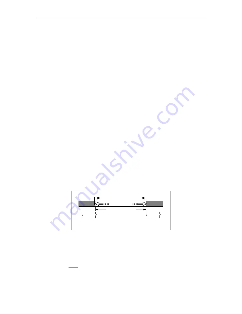
The drive can now be positioned only in the opposite direction.

max. positioning range

limit switch

software

mechan.

mechan.

software

limit switch

E2800059

The same also applies if a 2 (»

^

 start«) is programmed at storage location

3/73. In addition, when specifying a 

start signal the Controller first tests if the

nominal position of the new sentence would be beyond the limit values (this is
principally only possible for processing nominal lengths or if the limits have
been changed after programming of the nominal positions). In this case, the
limit switch will trigger including the effects described above.

Independent of the programming of storage location 3/73, the limit switch
function is always deactivated

Содержание GEL 8310

Страница 1: ... Copyright 12 97 by Lenord Bauer Co GmbH Subject to change without notice Operating Manual Positioning Controller GEL 8310 8610 GEL 8610 for 1 6 axis applications GEL 8310 for 1 3 axis applications ...

Страница 2: ...Lenord Bauer Co GmbH Dohlenstraße 32 D 46 145 Oberhausen Telefon 0208 99 63 0 Fax 0208 67 62 92 Internet http www lenord de E Mail info lenord de ...

Страница 3: ... the start and stop state 3 8 3 2 Programming mode for nominal values 3 9 3 2 1 Functions 3 10 3 2 2 Programming example 3 14 3 3 Programming mode for machine parameters 3 15 3 3 1 Functions 3 16 3 3 2 Programming example 3 18 Functional Descriptions 4 4 1 Definitions 4 1 4 1 1 Actual unit of measurement 4 1 4 1 2 Display units DispU 4 1 4 1 3 Count direction 4 1 4 2 Speed rates 4 3 4 3 Continuous...

Страница 4: ...put monitoring 4 31 4 11 2 Hardware limit switch option 4 32 4 12 Clock option 4 34 4 13 Linear path control 4 36 4 14 Program flow instructions 4 39 4 14 1 Call subroutine CALL Pr 4 40 4 14 2 Jump instructions JUMP Pr JMP sent 4 41 4 14 3 Signal dependent branching IF l O 4 42 4 14 4 Examples 4 43 4 15 Coordinates offset 4 46 Commissioning 5 5 1 Standard settings 5 2 5 2 Actual value adjustment 5...

Страница 5: ... Connector designations B 1 Terminal strip coding B 2 Module arrangement of the GEL 8310 back of the Controller B 3 Module arrangement of the GEL 8610 back of the Controller B 4 Connection diagrams B 5 Terminal strip N power supply B 5 Terminal strip P control inputs outputs B 6 Terminal strips C Z count input for incremental encoders B 7 Terminal strips W Y input for absolute encoders parallel B ...

Страница 6: ...s and coding C 8 Accessories C 11 Options C 11 Extensions modifications corrections etc Appendix D E available only if required Options Appendix O the content depends on the inserted option s Forms Appendix Y variable content Update Information Appendix Z please collect here the cover sheets of the updates supplied corrections etc ...

Страница 7: ... the safety features no uncontrolled re start of the controlled machine is possible If danger free operation can no longer be ensured the Controller should be taken out of commission and secured against accidental operation When servicing make sure that there is no voltage supplied to the whole controller i e including the built in module cards This applies in particular to relay cards used which ...

Страница 8: ...in this manual by special symbols DANGER This symbol denotes an imminent danger to life and health of persons Should you ignore these warnings severe damages to health or even life threatening injuries might be the consequence WARNING Symbolises a possible danger for life and health of a person Should you ignore these warnings severe damages to health or even life threatening injuries might be the...

Страница 9: ...Guarantee and liability claims on damages to persons or objects are excluded if they can be traced to one or more of the following causes implementation of the Controller outside the designated use inappropriate mounting installation and operation of the Controller operation of the Controller in conjunction with defective or non functional safety equipment in the system ignoring the instructions i...

Страница 10: ...f an index the table of contents at the beginning of the manual and of each chapter is very detailed thus facilitating the search for a specific information Optional functions are marked as such so that you may ignore this infor mation right from the start if your Controller is not equipped with these special functions For orientation purposes the individual chapters are briefly described below ch...

Страница 11: ...scriptions of software upgrades or modifications only available if required appendix O Description s of employed i e implemented options such as circular interpolation or synchronisation control GEL 8910 xxxx appendix Y A collection of forms and supplementary sheets if required appendix Z A collection of updating sheets for software upgrades or necessary corrections if available see also last poin...

Страница 12: ...dix Z in order to inform about the current software state of the manual 1 5 Characteristics of the Controller GEL 8310 8610 The menu oriented operating programming is performed using plain text either via the keyboard of the Controller or the optional PC program BB8110 single drives axes may be controlled separately or together as a so called unit exact dynamic close loop control with speed pre co...

Страница 13: ...escription of possible options Annex O or to possibly existing upgrading annexes appendix D E axis 3 axis 2 axis 1 3 3 3 3 3 3 3 3 start stop reset search for reference reversing switch reference coarse reference fine reference2 1 zero Delta_s keyboard lock sense 5 V encoder supply actual pos nominal pos reference pos reached forward reverse cancel controller lock release brake encoder supply 5 20...

Страница 14: ......

Страница 15: ... 8610 8 i 1 Introduction 1 1 1 1 General safety instructions 1 1 1 2 Designated use 1 3 1 3 Guarantee liability and copyright 1 3 1 4 Information on this manual 1 4 1 5 Characteristics of the Controller GEL 8310 8610 1 6 ...

Страница 16: ...ext higher functional level 5 Function keys activation of a certain function in combination with another key see section 2 3 6 Slot for memory card option to read or write operating data 7 Data keys to input values in the programming mode 8 ENTER key storing of an entered value or operating function confirming messages of the Controller 9 FORWARD cursor key scrolling forward through value and func...

Страница 17: ...mode for nominal values N select unit O P increment decrement axis no Q inquire date time of error occurrence option R insert sentence S automatic mode T U enter search reference measure V enter correction value W call up fault memory X go to the beginning of the next previous sentence Y manual operation in combination with Z Ä Ö Ü Z Ä fast slow speed reverse Ö Ü slow fast speed forward SHIFT swit...

Страница 18: ... with serial interface with clock only 0 A list stored faults 1 A enter a reference value 1 N absolute coordinates offset 2 N relative coordinates offset 2 A search for reference 3 A enter correction value 4 A enter value of park position 9 N Teach in operation ON OFF A slow speed reverse A slow speed forward N beginning of previous sentence N beginning of next sentence N store and go to the next ...

Страница 19: ...ct program 1 N program flow instruction CALL Pr 2 N program flow instruction JUMP Pr 3 N program flow instruction JMP Sent 4 N program flow instruction IF I O 7 M N clear memory delete unit or program 8 N copy sentences 9 N define the end of program N delete sentence A decrement axis for display within the unit A increment axis for display within the unit N jump to the beginning of program N jump ...

Страница 20: ...OPERATIONAL CONTROLS 2 8310 8610 8 i 2 Operational Controls 2 1 2 1 Basic keyboard 2 1 2 2 Additional keyboard of the GEL 8610 2 2 2 3 Function key combinations 2 3 ...

Страница 21: ...ine parameters password password system storage no parameter 1 parameter 2 parameter 3 unit program sentence AUTOMATIC MODE PROGRAMMING MODE FOR NOMINAL VALUES program p sent x sent y program n nominal value 1 nominal value 2 end of program nominal value 1 nominal value 2 axis 1 6 unit 1 6 storage no parameter 1 parameter 2 parameter 3 parameter x storage no parameter 1 parameter 2 parameter 3 pla...

Страница 22: ...lied at the stop input of the respective unit terminal P4 P7 P10 Low level is applied at the reset input of the respective unit terminal P5 P8 P11 Activation positive signal edge at start input P3 P6 P9 via a serial interface With each further start signal the next sentence of the program or another piece will be processed Within the started state further start signals may also be generated auto m...

Страница 23: ...e In this state several direct entries or an automatic search routine may be performed described in the following section Only if the Controller is in the reset state for all units data can be read from the optional memory card Activation High level at reset input P5 P8 P11 selecting a storage location in the programming mode of machine parameters via a serial interface Standard display axis outpu...

Страница 24: ...tion text of the value displayed in C cf section 3 1 2 1 Select a program only possible in the reset state and if the appropriate unit parameter 2 6 0 keyboard 0 N Select a unit for the display if the unit includes more than one axis the one with the lowest number will be shown by means of the following two functions the desired axis can then be select O Select an axis for the display increment ax...

Страница 25: ...p input P4 7 10 refer also to section 4 6 2 3 V Direct entry of a correction value for an axis to be selected only possible in the reset state and if the machine parameter 3 7 of that axis has been programmed accordingly refer also to section 4 7 abort with the value becomes active with the next start signal 4 Direct entry of the park position for an axis to be selected only possible in the reset ...

Страница 26: ...Write data to memory card option storing of operating and machine parameters with security inquiry refer also to storage location 1 6 GEL 8310 or 1 9 GEL 8610 respectively Read data from memory card option loading of operating and machine parameters only possible if the Controller is in the reset state for all units and the card has at least already once been written with security inquiry Y Ö Manu...

Страница 27: ...eed reverse see explanations of slow speed forward Y Z Manual operation fast speed reverse see explanations of slow speed forward Y _ Manual preset of the signal actual nominal P27 P28 P29 as this is an axis function the axis to be controlled first has to be displayed see further above 0 and ...

Страница 28: ...nal speed rate 1 identification text for the selected axis GEL 8310 input only via serial inter face 1 under preparation voltage at analogue output 2 standard tolerance of position contouring error 2 nominal cycles actual cycles variance of the cycles act values of 3 connected axes here display A axis 2 display C axis 3 display B axis 1 2 1 These parameters can only be selected if the appropriate ...

Страница 29: ...tem parameters see appendix A and have a common start stop and reset input each for the combined axes Each program can consist of a different number of sentences When pro gramming nominal values the end of program has to be defined after the last sentence via a special key combination refer to the following section it is handled within the system like an individual sentence which however only cont...

Страница 30: ...e or unit structure is to be changed at a later time all programs of this unit will be deleted when you confirm the security inquiry Delete unit with start will cause no action then 3 2 1 Functions The following keys and key combinations are available in the programming mode for nominal values to call up certain functions 0 S Terminate the programming mode of nominal values and change to automatic...

Страница 31: ... the entry made and change to the next nominal value of the same type within the program quick input so you can input all the position values e g directly one after the other skipping the other nominal value types for the moment Delete a preset or entered value L Delete a sentence without security inquiry only possible if the Controller is in the reset state for all units the numbers of the follow...

Страница 32: ...f the sentence end number entry overwrite the sentences following the actual one insert the sentences before the actual one R In the first case there must still be as many sentences after the actual sentence in the destination program as shall be copied otherwise an error message will be issued 0 I H Change between position and length the entered position value is interpreted either as absolute po...

Страница 33: ... place of the nominal value type position or length see section 4 15 2 Relative coordinates offset at the beginning of the sentence only in place of the nominal value type position or length see section 4 15 9 B Activate teach in operation this function can only be activated at nominal value type position absolute dimensions and is identified by an appropriate plain text in display C the drive can...

Страница 34: ... 2 axes program no 3 sentence no 12 is to be changed from 45 20 to 45 50 E183062B With the GEL 8610 key M can be used instead of 0 The password inquiry will only appear if an appropriate arrangement with respect to the machine parameters has been made refer to appendix A system parameters With the GEL 8610 key S can be used instead of 0 ...

Страница 35: ...it parameters specify for each unit consisting of one or more axes which nominal values shall be included in a sentence and which other preset values shall apply for all axes of this unit With the axis parameters the Controller is matched to the different drives axes actual value processing calibration control etc To avoid an unauthorised access to the data the programming mode can only be activat...

Страница 36: ...meters will be actualised in the RAM of the Controller status message in display B Loader this also applies if the programming mode is left via the key Cancel input or abort selection function and return to the next higher selection or programming plane Confirm the selection made or value entered and change to the next parameter Respond to a security inquiry with yes any other key means no Delete ...

Страница 37: ...le inside of the axis parameter plane at first the axis whose parameters shall be used has to be selected source axis the parameters of the active axis whose parameters are just displayed destination axis will be overwritten execute the copy function with or abort with Q Set the date time with optional serial interface module with real time clock only this is only possible directly after entering ...

Страница 38: ...ng example The switching level of the reversing switch signal storage location 3 14 for axis 2 shall be inverted change of travel direction at Low signal without storing S E180062C S It is assumed that 3 axes are connected and assigned to one unit 1 therefore no other units or axes can be selected ...

Страница 39: ...Automatic mode 3 2 3 1 1 Functions 3 4 3 1 2 Displays in the start and stop state 3 8 3 2 Programming mode for nominal values 3 9 3 2 1 Functions 3 10 3 2 2 Programming example 3 14 3 3 Programming mode for machine parameters 3 15 3 3 1 Functions 3 16 3 3 2 Programming example 3 18 ...

Страница 40: ...r a resolution of 1 hundredth Value 100 mm entered 100 or 100 or 100 0 or 100 00 always indicate 100 00 Position values are always specified in actual unit of measurement Nominal speeds can also be pre defined either in actual unit of measurement per second or in an other unit see section 4 2 4 1 2 Display units DispU In this manual display units abbreviated to DispU mean a sequence of digits with...

Страница 41: ...vement in the wrong direction Correspondingly this is also valid for reverse positioning with upward counting On the supposition that the position loop control is disabled for the interrupted and reset state storage location 3 47 0 then this process can be aborted either manually by specifying the stop or reset signal or automatically if a not too large maximum contouring error value has been prog...

Страница 42: ...lution of the speed values the number of decimal places has to be fixed in storage location 3 46 The following facts apply For each decimal place by which the speed resolution is higher than the actual measure resolution the point of the value in a must be shifted to the left i e the value must be divided by 10 For each decimal place by which the speed resolution is less than the actual measure re...

Страница 43: ...facts are represented again for those who prefer to work with mathematical formulas c D A c v DA DD v 10 100 cv conversion factor according to Spd mult at storage location 3 45 D desired unit of length or angle per each unit of time for the speed A actual measuring unit per second default unit of the speed DA number of decimal places in the actual value display storage location 3 5 DD number of de...

Страница 44: ...e entered with only one decimal place DD 1 then cv 16667 10 16 6667 1 with 3 decimal places DD 3 cv 16667 10 01667 1 Example 2 Irrespective of the actual measuring unit used in the equipment e g mm resolution 0 1 mm the speed rates of the drive shall be entered in revolutions min rpm without any decimal places This corresponds to a distance of 10 0 mm with 1 revolution D mm A mm DA DD c mm mm mm v...

Страница 45: ...set of the position is equal to the programmed nominal value Thus the machine is moved at a constant speed or accelerated to its nominal position i e without braking phase Variant 3 of storage location 2 3 can only be used together with the linear path control refer to below If several axes are combined to one unit refer to storage locations 1 3 to 1 5 resp 1 8 then a continuous sentence processin...

Страница 46: ... time If the result shows a difference positive negative contouring error Delta_s to be shown in display C then this difference is converted using the proportional action factor Ksp to an equivalent speed value vk This value is then added to the time dependent nominal speed value vt The control dynamics Ksp can be adjusted according to requirements storage location 3 33 The ratio of the speed v to...

Страница 47: ... the jerking time is programmed the smaller is the jerk i e the softer the drive runs during starting and stopping The following diagram illus trates these relations by the example of 3 different jerking times tj s DispU speed position nom t 2 t 1 t 3 example 1 for t example 2 for t example 3 for t j1 j2 j3 t t t j1 j2 j3 v DispU sec jerk accelerating braking a 1 2 j j 3 j b j DispU sec 3 a b Disp...

Страница 48: ...he possible connection of a 5 V encoder to the first count input of module C 5 V module C 4 3 2 5 6 7 8 9 10 1 0 0 90 90 Zero Zero increm encoder sense E180014C 4 5 2 Fault The fault signal at terminal 30 of the 1st module P1 becomes active level changes from High to Low when the following situations occur the Delta_s contouring distance exceeds one of the programmed Smax values storage locations ...

Страница 49: ...ring distance Delta_s causing a correspondingly high control voltage No fault is generated in the Controller if Delta_s stays below the Smax maximum value storage location 3 42 44 When powering up the drive system the next time the control voltage generated then by the Controller may cause an inadmissible high loading of the drive To prevent this the contouring distance for the corresponding axis ...

Страница 50: ...using storage location 2 9 refer to the Pin Layout in appendix B The signal reset can only be output in lieu of the signal sentence end or block end Sentence end is output with a start signal if the actual number of pieces is equal to the nominal number of pieces If the number of pieces is not part of a nominal value sentence storage location 2 1 1 or 3 then the signal is output at the start of ea...

Страница 51: ... signal is output if the Controller is in the reset operating state It is reset for the corresponding unit as long as the drive is manually positioned or is in the automatic reference search routine 4 5 6 Range signals These signals are axis related They occupy a certain BCD decade 4 bits at a data output module A L or R which has to be determined using storage location 3 61 refer to the Pin Layou...

Страница 52: ...es 200 0 100 0 0 0 100 0 200 0 actual position start 100 0 Rx 1 0 end 200 0 end 100 0 1 0 start 200 0 E180010A Relative ranges Storage location 3 62 1 Signals are output in the started state only 100 0 200 0 300 0 400 0 500 0 nominal Rx 1 0 variance 0 start 100 0 end 200 0 variance 0 1 0 end 100 0 start 200 0 actual position E180010B ...

Страница 53: ...rt value of R4 are set internally to a maximum value Programmed values are ignored 100 0 200 0 300 0 400 0 500 0 nominal R2 fast speed actual position 1 0 variance 0 1 0 start variance 0 forward reverse R1 slow speed 1 0 start 100 0 end 50 0 R3 forward 1 0 start 20 0 R4 reverse 1 0 end 50 0 end start end 150 0 start 200 0 v speed profile 0 E180010C Storage location assignment slow speed 3 63 R1 Be...

Страница 54: ...rive control is only possible in the interrupted or reset state of the automatic mode and during the teach in operation when programming nominal values The following diagram is based on the fact that the polarity for manual controlling has not been changed storage location 3 20 0 1 0 key or signal R1 slow speed 1 0 R3 forward 1 0 R2 fast speed 1 0 R4 reverse 1 0 1 0 1 0 t key or signal key or sign...

Страница 55: ...grammed values for the start and end are ignored Further explanations on reference search routine are contained in section 4 6 2 The following diagram assumes that the reference measure is set at forward traversing storage location 3 11 1 1 0 search for reference v speed profile 0 reference reached 1 0 R1 slow speed 1 0 R3 forward 1 0 R2 fast speed 1 0 R4 reverse 1 0 1 0 reference fine 1 0 reversi...

Страница 56: ...ating state of the automatic mode The displays show the following information display A max 8 signal states 0 Low 1 High display B text Status display C identification of the module and the connections signals decades Via the keys you can scroll through the various display groups will abort the function Example show the signal states at terminals 11 18 of module P1 E180062D High level at P4 stop u...

Страница 57: ... 30 27 module D1 terminals 10 9 8 7 20 19 18 17 30 29 28 27 D2 10 7 D2 20 17 D2 30 27 GEL 8610 only module D2 terminals as above signals reference fine 3 digits Z1 RF3 1 module Z1 C1 terminal 29 19 9 axis 3 2 1 Z2 RF6 4 GEL 8610 only module Z2 C2 terminal 29 19 9 axis 6 5 4 data output 8 digits A1 D1 D0 A1 D3 D2 A1 D5 D4 module A1 pin 17 4 16 3 15 2 14 1 decades 1 0 21 8 20 7 19 6 18 5 decades 3 2...

Страница 58: ... D0 E1 D3 D2 E1 D5 D4 module E1 pin 17 4 16 3 15 2 14 1 decades 1 0 21 8 20 7 19 6 18 5 decades 3 2 25 12 24 11 23 10 22 9 decades 5 4 E2 D1 D0 E2 D3 D2 E2 D5 D4 module E2 pins as above E3 D1 D0 E3 D3 D2 E3 D5 D4 module E3 pins as above E4 D1 D0 E4 D3 D2 E4 D5 D4 GEL 8610 only module E4 pins as above ...

Страница 59: ...tion 3 85 The reference measures can either be programmed in the programming mode of machine parameters or directly in the reset state of the automatic mode via the 1 key combination precondition storage location 3 9 1 ref val or 3 val auto Direct entry of a reference measure Press the 1 key combination resp the T key GEL 8610 Enter the axis number and confirm with Enter the reference value displa...

Страница 60: ...ge location in the machine parameters programming mode 4 6 2 Automatic reference search routine If a value unequal to 0 has been programmed at storage location 3 11 and High level is applied to the stop input of the respective unit a reference search routine for the machine can be initiated in the reset state of the automatic mode The storage location determines the direction of travel where the r...

Страница 61: ...determined at storage location 3 14 the direction of travel is reversed and the speed rate is reduced to the value determined at storage location 3 17 The drive now moves towards the reference position Once this point has been passed reference coarse fine signals the actual value counter display A is set to the reference measure the drive is stopped and the reference reached signal is output This ...

Страница 62: ...us nominal position length programmed length correction value c incremental dimensions counter value at start set to correction value residual value target position programmed nominal length The correction value is programmed at storage location 3 6 either in the machine parameters programming mode or directly in the reset state of the automatic mode precondition storage location 3 7 1 active Dire...

Страница 63: ...value is internally set to zero and the maximum value to rotary table range 1 DispU independent of the values programmed at storage locations 3 71 and 3 72 In addition the software limit switch function will be ignored if it is activated storage location 3 73 Counting example for a defined rotary table range of 360 0 actual measuring units counting up 359 8 359 9 0 0 0 1 0 2 counting down 0 2 0 1 ...

Страница 64: ...ed 3 8 360 0 0 3600 4 1 4000 0 Only positive values can be entered for the setting of lengths nominal values In operation negative lengths are however achieved for values that are larger than half of the counting range Thus a certain travelling direction can be forced for the drive by an appropriate selection of the nominal length Example with the data from the previous exampIe desired nominal len...

Страница 65: ...avelling to the park position and remaining there display B shows Par instead of the sentence number At the same time the machine functions programmed at storage location 3 60 are output at the fixed data output module refer to appendix A Storage location 3 56 specifies when the parking position is to be reached The following diagram gives an example illustrating the possibilities for a program wi...

Страница 66: ...orage location 3 19 hardware limit switches storage location 3 74 nominal position length storage location 3 75 correction value storage location 3 76 speed rate storage location 3 77 With the next start signal the BCD data nominal values program and sentence number are taken over by the Controller Nominal values are only effective if a program has already been selected All nominal values must be ...

Страница 67: ... MSB position if programmed accordingly refer to storage location 3 80 and following Low level will be output as long as the data are not stable min 100 msec data data ready abt 20 msec E180033C In addition a sign bit can be specified for the output If not specified the full 6 decades are available for the value In the other case the sign is output as MSB or when evaluating the data ready signal a...

Страница 68: ... unit shall simultaneously be available at the first data output A1 Programming storage location variant meaning 2 2 2 8 out1 2 8 machine functions at decades 2 3 2 8 1 output 1 sentence and program number at decades 0 2 4 5 2 9 3 out 1 3 program processing signals at decade 3 Output a sentence and program number at decades 0 1 and 4 5 the 3rd digit of the sentence number at decade 2 must be zero ...

Страница 69: ...4 30 4 10 External data input output FUNCTIONAL DESCRIPTIONS 8310 8610 8 For your own entries 13 12 11 10 9 8 7 6 5 4 3 2 1 25 24 23 22 21 20 19 18 17 16 15 14 5 4 3 2 1 0 A_ X180053B ...

Страница 70: ...driving is programmed in storage location 3 73 Once the upper or lower limit is exceeded a braking process is initiated the fault signal is output at terminal P130 level changes from High to Low the separation points in display B are flashing only visible if the corresponding axis is just displayed The drive can now be positioned only in the opposite direction max positioning range limit switch so...

Страница 71: ...tware version 11 xx is replaced by a newer version any possibly built in inverter circuits have to be removed or they now have to be inserted If a limit switch is triggered the Controller reacts as if a software limit switch has been triggered refer to the previous section Furthermore a corresponding error message is stored in the error memory refer to section 6 2 error numbers 28 and 29 The confi...

Страница 72: ... axes are connected to decade 0 of the E2 data input module and the ones of 4th and 5th axes to decade 2 of the same module 0 1 2 E2 1 2 3 4 5 6 14 15 16 17 18 19 decade MIN MAX MIN MAX axis 1 axis 2 MIN MAX MIN MAX axis 5 axis 4 limit switch 2 2 2 2 2 2 2 2 2 2 2 2 0 1 2 3 0 1 2 3 0 1 2 3 E180053C ...

Страница 73: ...77C For the indication of fault time values refer to paragraph 6 2 As long as the time is indicated no other function can be activated at the Controller The clock function is terminated by means of the key then displays B and C again indicate the normal operating data Setting the clock The clock is set within the programming mode of machine parameters i e immediately after having activated the pro...

Страница 74: ...l input position now shifts to minutes Enter the values for minutes and hours as described above for the seconds After having entered the hours the input position shifts to the calendar day Enter calendar day month and year as described above After having entered the year the function recommences Effect further modifications as described above or quit the function with the latter is possible at an...

Страница 75: ...ng the speed rate for the combined axes separately for each sentence In this case the speed rate nominal value type must be part of the sentence determined at storage location 2 3 The input format or the measuring unit for the speed rate is fixed by the first axis of the unit storage locations 3 45 and 3 46 refer to section 4 2 identically for all sentences In this case the speed rate nominal valu...

Страница 76: ...nd the following section Spline A spline function can be used to avoid jerky speed rate changes infinite acceleration with path controlled axes in the case of angular paths and continuous sentence processing Herewith the maximum appearing acceleration for one slave drive is limited to the sum of the accelerations of two drives master and slave here master is always the axis that has to travel the ...

Страница 77: ...8 acceleration and speed rate of the involved axes The restriction described in section 4 3 is not valid for this function The following figure shows some typical path courses A B C nominal values programmed S automatic start A C B A C B S S A B C S A B C S E180093G ...

Страница 78: ...ombination as this is the case at the change over between position and length A change over between the different instructions is however possible If an instruction is to be cancelled or to be replaced by a normal sentence the corresponding instruction sentence is first to be deleted resp L When inserting a normal sentence using resp R then the sentence currently being active must also be a normal...

Страница 79: ...ing at the sentence following the CALL instruction Up to 20 CALL instructions can be nested If the number is exceeded the program is interrupted at the corresponding position and the error 32 Too many CALLs is stored in the fault memory can be retrieved using 0 If another program is called from a subroutine CALL with JUMP then after processing the other program a jump is made back to the program t...

Страница 80: ...tions which means that they do not interrupt a JUMP chain This counter is however reset to zero by a positioning process or an IF instruction If another program is called from a subroutine CALL with JUMP Pr then after processing the other program a jump is made back to the program that originally contains the CALL instruction processing continues with the sentence following the CALL instruction In...

Страница 81: ...n assignment of a function is not required When starting from the reset state it is not possible first to process an IF in struction directly in the first sentence of the started program or via a CALL JUMP instruction from another program just started so as to avoid non defined initial positions In this case the program is immediately aborted in a way the Controller remains in the reset state Erro...

Страница 82: ...el at position 2 0 or 2 1 of the 2nd data input program 2 is to be processed otherwise program 3 Program 1 control program sentence 1 Pos A 1 0 initial position sentence 2 IF I O 200 bit 20 1 sentence 3 JMP sent 8 yes process program 2 sentence 4 IF I O 201 no bit 2 1 1 sentence 5 JMP sent 8 yes process program 2 sentence 6 CALL Pr 3 no process program 3 sentence 7 JMP sent 2 ready back to the fir...

Страница 83: ...tence 1 Pos A 1 0 initial position sentence 2 IF I O 200 bit 2 0 1 sentence 3 JMP sent 5 yes next scan sentence 4 JMP sent 7 no process program 3 sentence 5 IF I O 201 bit 21 1 sentence 6 JMP sent 9 yes process program 2 sentence 7 CALL Pr 3 no process program 3 sentence 8 JMP sent 2 ready back to the first scan sentence 9 CALL Pr 2 process program 2 sentence 10 JMP sent 2 ready back to the first ...

Страница 84: ...tarted e g every 5 sec The process enable is scanned in a waiting loop signal at position 20 of the 2nd data input 1 start enabled Program 1 sentence 1 Pos A 1 M funct 0 0 beginning of material do not drill sentence 2 IF I O 200 start permitted sentence 3 JMP sent 5 yes next scan sentence 4 JMP sent 2 no repeated scan waiting loop sentence 5 IF I O 202 end of material sentence 6 JMP sent 1 yes ini...

Страница 85: ...50 C rel A1 400 C rel A2 250 C abs A1 600 C abs A2 100 E180039B If a sentence is started with a coordinates offset only the actual value counter of the concerned axes is changed No positioning process is involved Then the next sentence is started with an internally generated signal If it contains the nominal length 0 for all axes then here also no positioning is performed Requirements for all invo...

Страница 86: ...moved to With the second starting signal the actual values of axis 1 and axis 2 are set to 100 coordinates offset and then with an internal start the position P2 is moved to with reference to the machine zero point the coordinates would be 200 300 Position P3 is moved to with the third starting signal The machine zero point is reactivated with the next reset signal i e the displayed actual values ...

Страница 87: ...low instruction single processing of the work piece program no 2 Coding for serial transmission length 4 bytes byte 4 MSB 3 2 1 LSB absolute Exh xxh xxh xxh relative Dxh xxh xxh xxh value of the offset negative two s complement If a normal sentence contains further elements such as e g the number of pieces then the values for these will must be transferred following the coordinates offset even if ...

Страница 88: ...e control signals 4 10 4 5 5 Program processing signals 4 11 4 5 6 Range signals 4 12 Absolute ranges 4 13 Relative ranges 4 13 Drive signals 4 14 4 5 7 Display of the signal status 4 17 4 6 Reference measure 4 20 4 6 1 Setting of the reference measure when positioning the drive 4 20 4 6 2 Automatic reference search routine 4 21 4 7 Correction value 4 23 4 8 Rotary table positioning 4 24 4 9 Parki...

Страница 89: ... 13 Linear path control 4 36 4 14 Program flow instructions 4 39 4 14 1 Call subroutine CALL Pr 4 40 4 14 2 Jump instructions JUMP Pr JMP sent 4 41 4 14 3 Signal dependent branching IF l O 4 42 4 14 4 Examples 4 43 4 15 Coordinates offset 4 46 ...

Страница 90: ...rogramming procedure or setting are marked with Prerequisites initial state You have already made yourself familiar with the operating and the func tions of the Controller by reading this manual The electrical connections to the peripheral equipment encoders drive amplifiers initiators etc have already been established according to the connection diagrams in appendix B Motor amplifier and tachomet...

Страница 91: ...n your control device program Otherwise the EEPROM and consequently the Controller will break down after a relatively short operational time with the display showing EEPROM error 5 1 Standard settings Activate the programming mode for machine parameters 1 9228 System parameters Storage locations 1 3 to 1 5 GEL 8610 1 8 units Combine the axes available into units according to the installation requi...

Страница 92: ...l value display Example actual 1000 increments revolution desired 820 incre ments revolution multiplier 0 82 Storage location 3 5 decimal point The number of decimals depends on the requested resolution Example actual 820 DispU required 82 0 actual measuring units mm with a resolution of 1 10 mm decimals 1 X X Now the adjustment of the actual value for the incremental encoder of the treated axis i...

Страница 93: ... the logic level of the signal Determination of the encoder s type of logic for Gray or BCD code If the encoder has not yet been attached to the drive or may easily be dismounted turn the encoder axis and observe the actual value display does the actual value change erratically the logic reverse must be programmed If this possibility of testing is not given checking must be performed as soon as th...

Страница 94: ...250 238 307 200 DispU 557 438 DispU This value however is above the counting range and that means the mechanical zero point of the angle encoder is located inside the displacement area Measure the axis of the angle encoder must be turned back by at least 33 150 DispU then the count display would read 217 088 DispU in the machine s zero point and the mechanical zero point of the angle encoder is ri...

Страница 95: ...x This value is determined by the maximum speed of the drive vmax system dependent e g 8 50 V for vmax 3000 rpm Storage location 3 32 maximum speed rate vmax This is a installation specific value and indicates the speed in actual measuring units per second at output voltage Umax For the moment it is sufficient to indicate an estimated value or a value calculated from the installation data Later on...

Страница 96: ...appendix O When setting to 0 the value of another time parameter is used tbrake taccel for 3 38 0 tbrake taccel for 3 37 0 taccel taccel for 3 36 0 Storage location 3 42 and 3 43 contouring error Smax A maximum contouring error is to be determined for safety reasons so that the drive can be stopped if a wrong travel direction has been set for the control refer to next section The values should be ...

Страница 97: ... move forward as requested exchange the count connections 0 90 of an incremental encoder at the Controller or reverse the count direction storage location 3 2 and exchange the connections of the amplifier input or analogue output only feasible if the amplifier inputs of the several axes are not inter connected through a joint earth line see terminal strip D in appendix B or reverse the polarity of...

Страница 98: ...ly only possible for absolute encoders with BCD or Gray code select the appropriate code type on storage location 3 1 with logic reverse The next step is to determine the minimum voltage values for the drive amplifier which is necessary to start the drive in the forward and reverse direction if not yet known ...

Страница 99: ...e display staying constant At a certain voltage value the drive will start moving forward which you will recognize by the fact that the actual value display changes by 1 increment sec 1 DispU sec Remember the voltage value and repeat this procedure once or twice Return to the programming mode for machine parameters Storage location 3 29 minimum positive voltage value Umin Enter the largest of the ...

Страница 100: ...s connection that potential nonlineari ties in the drive system can lead to major control deviations when position ing later on Exit the programming mode for machine parameters Ensure that the axis to be adjusted is displayed The display must show the output voltage select with Move the drive at slow speed forward or reverse until the voltage value U belonging to the working speed v is constant Re...

Страница 101: ...the entire displacement process In the affirmative reduce the control factor accordingly output voltage forward reverse Ksp too big good forward reverse E180016C Tip An unstable control behaviour may also be recognized by the displayed value for the output voltage oscillating more intensively when travelling at constant speed 5 6 3 Accelerating braking times The values for taccel taccel tbrake and...

Страница 102: ...ring distance Delta_s major fluctuations during accelerating or braking indicate that the appropriate values are too small Times being too long are uncritical for the control but do however negatively influence the duration of positioning The Controller limits the values to a maximum size which however can only be attained under most unfavourable conditions see storage location 3 35 in appendix A ...

Страница 103: ...teristic of the drive is fixed refer to section 4 4 2 Storage location 3 39 jerk time tjerk Set the value by manually displacing at low speed rate working speed in such a way that the drive shows the desired behaviour for the later posi tioning procedures Note Because of internal calculation reasons the jerk time is limited to a maximum value see storage location 3 39 in appendix A Now the control...

Страница 104: ...s Storage locations 3 9 17 calibration functions and values if incremental encoders are used Storage location 3 20 adaptation of the keys and or signals for the manual drive control to the installation specific directions Storage locations 3 21 24 absolute speed values for the manual drive control Storage locations 3 27 and 3 28 switch off points Sdead for control stabilization in the nominal or i...

Страница 105: ...610 8 Storage locations 3 56 60 functions and values for a parking position Storage locations 3 61 70 functions and values for range signals Storage locations 3 71 74 input control monitoring and limit switch functions Now first commissioning is completed ...

Страница 106: ...5 3 5 2 2 Absolute encoders 5 3 5 3 Preparations for displacing the drive 5 6 5 4 Count direction and voltage polarity 5 8 5 5 Minimum voltages 5 10 5 6 Optimization of control parameters 5 11 5 6 1 Maximum speed 5 11 5 6 2 Control factor 5 12 5 6 3 Accelerating braking times 5 12 5 6 4 Jerk time 5 14 5 7 Controller configuration 5 15 ...

Страница 107: ...he order in which they are dealt with The descriptions do not represent the whole range of possibilities Messages valid only for certain options are dealt with at their corresponding descriptions refer to appendix O Messages Delete memory Delete program Delete unit EEPROM error Fatal error 1 Inactive auto cal Inactive entry Invalid auto cal Invalid delete Invalid entry Invalid pieces Invalid prog ...

Страница 108: ... the 7 keys resp F have been pressed instead of entering the sentence number Confirm safety inquiry with or abort function with any other key Delete unit In the nominal value programming mode the 7 keys resp F have been pressed after selection of the unit instead of the program number input Confirm the safety inquiry with or abort function with any other key In the machine parameter programming mo...

Страница 109: ... cal automatic calibration function is inactive You tried to start an auto matic reference search routine 2 resp U although this function has not been enabled in the machine parameters for the respective axis Enable this function at the corresponding axis para meter storage location 3 9 Inactive entry In the Automatic mode you tried to select a program 1 or to enter a reference value a correction ...

Страница 110: ...entence of a program or the end of the program itself resp L Acknowledge with any key Invalid entry In the Automatic mode you tried to change the program 1 or the direct entry of a reference value a correction value or a parking position was activated 1 3 4 although the unit of the respective axis has not been reset Reset the Controller for the respective unit In the nominal value programming mode...

Страница 111: ... be inserted Invalid program When copying sentences 8 resp C a non existent program has been specified as source Enter a correct program number When powering on the device you had switched off while the message Saving pro gram has been issued or the device is defect Clear all nominal value storage locations i e carry out the clearing pro cess for each programmed unit then switch the device off and...

Страница 112: ... card error Memory card used is de fect or has been used so far with another Controller type GEL 8310 GEL 8610 Use another card You tried to read a card which has not been written yet check sum error Exchange the card or select write instead of read You tried to read all para meters although the axis parameters have not been stored on the card in all the previous writing processes Modify the stora...

Страница 113: ...quired delete sen tences in another program in order to free up new memory space Only for s begin at the beginning of the sentence only For a sentence already begun i e starting with the second or a further nominal value in the actual sentence you tried to define the end of program 9 resp K or to set a program flow instruction at this position 1 4 First enter the remaining nominal values of the ac...

Страница 114: ...eter occurs when trying to exit the programming mode of machine parameters Confirm the message with the invalid parameter is activated and can now be corrected If the message is acknowl edged with e g i e ignored no unit can be started and the programm ing mode of nominal values cannot be activated In such a case change an arbitrary parameter save it and exit the programming mode Then the invalid ...

Страница 115: ...ram already exists You tried to redefine the end of program for an already established program 9 resp K Acknowledge the message with any key Prog end missed missing end of program You tried to exit a still empty or newly created program or 0 resp S Entries have already been made do not con firm the message with the program is not exited and define the end of program 9 resp K An empty program has b...

Страница 116: ...ltiplier and a decimal point for the speed rate input storage locations 3 45 and 3 46 Enter a lower value write m card write memory card The keys resp have been actuated in order to safe the machine para meters and nominal values on the memory card inserted Confirm with or abort with any other key Write protect You tried to write on a memory card although the write protection has been activated at...

Страница 117: ...system fault c c current number of indicated fault 1 20 t t total count of faults stored 1 20 n n identification no of the fault see table Display B C plain text of the fault see table If the Controller is equipped with a serial interface module V with clock the date and time of the occur rence of the fault can be displayed resp Q Example A reference search routine is released for an axis of the 2...

Страница 118: ...Table of faults No Displays B C Unit Axis Description 1 Pos Pos max X Actual position exceeds the Pos max software limit switch storage location 3 72 refer to section 4 11 1 2 Pos Pos min X Actual position is less than the Pos min software limit switch storage location 3 71 refer to section 4 11 1 3 Pos Pos max X Nominal position exceeds the programmed Pos max maximum value storage location 3 72 r...

Страница 119: ...or reference signal was preset during the programming of machine parameters 12 MemEdit auto cal X Search for reference signal was preset during the recalculation of machine parameters i e directly after terminat ing the programming operation 13 stop start X Start signal was preset with Low level at the stop input 14 reset start X Start signal was preset with High level at the reset input 15 autoCa...

Страница 120: ... aborted by the modification and recalculation of machine parameters 25 m Drive MemEdit X Manual positioning was aborted by the modification or recalculation of a ma chine parameter 26 framing error Stop bit error at the serial interface wrong polarity Low level 27 ser com error Error during serial transmission parity overrun check 28 axis in HW max X Axis triggered the upper hardware limit switch...

Страница 121: ...meter error has not been removed refer to section 6 1 Param error Axes which are still not associated to a unit system parameters can of course also not be started The following causes no fault message can be the reason why a drive cannot be positioned manually although the corresponding storage locations are correctly programmed no High level is present at the stop input of the corresponding unit...

Страница 122: ......

Страница 123: ...TROUBLE SHOOTING 6 8310 8610 8 i 6 Trouble shooting 6 1 6 1 Warning and error messages 6 1 6 2 Fault memory 6 12 ...

Страница 124: ...n wire end ferrules will be advantageous For tightening the terminal screws use a screw driver with the following blade size 0 4 2 5 mm for terminal strips with a 3 8 mm grid screw M2 as C D P W Y and Z 0 5 3 5 mm for terminal strips with 5 1 mm and 7 6 mm grids screw M3 as N and R 7 2 EMC measures In order to achieve highest electromagnetic compatibility EMC or to maintain EMC certified for the d...

Страница 125: ...ronic earth connections measures should be taken so that no compensat ing currents can flow through the screen e g potential equalisation line with large cross section or cable with double screen where only one end of each screen is to be connected at different ends If inductive loads relays contactors are connected to the logic outputs measures for spark suppression should be provided recovering ...

Страница 126: ... to the mounting plate using the twin blade terminal 6 3 mm on the transformer Connect the mains earth wire resp the screen of the mains cable coming from the filter to the PE labelled terminal Connect the screen of the Controller supply to the twin blade terminal on the transformer c Controller Each inserted module is earthed via a special contact socket in the upper metal angle metal frame with ...

Страница 127: ... Fig 1 here Controller GEL 8310 without CE certification E183083A 7 3 1 Disassembly Remove optional memory card if inserted devices with certification devices without certification Unplug all connectors from the modules Remove 4 recessed head screws at the corners of the metal frame with the GEL 8610 there are 2 additional screws in the middle top and bottom Disconnect earth wire from the metal an...

Страница 128: ...o that they cannot be confused later on 7 3 2 Assembly Insert the module in the guiding rails and push it in The Controller housing contains each 2 adjacent guiding rails Both power and P1 modules see Fig 1 are to be inserted into the left guiding rails All other modules are to be inserted into the right rails see also appendix B under Module arrangement If a module strucks or blocks during insert...

Страница 129: ...d socket Place the metal angle Mind that all earth pins of the modules fit correctly in the associated sockets of the metal frame angle Screw the metal frame Plug all connectors and terminal strips Screw the metal angle and strip including the twin blade terminal for earthing Connect earth wire to the metal angle Mind that the cable lug does not contact the screw of the heat sink In this case inte...

Страница 130: ...ent all modules and blind plates have to be removed from the Controller GEL 8610 on the right half only the P module may be excepted from this with built in memory card option Disconnect all current sources from the Controller Remove modules as described in section 7 3 1 The EPROM is accessible now It will advantageously be removed from the socket by means of a special extractor tool Starting from...

Страница 131: ...n the chip relief in the socket a round indentation in the bevel of the memory chip ATTENTION A wrongly inserted EPROM can cause hardware defects that may not be sensible Therefore check the correct orientation of the chip before assembling the device Insert modules and assemble the Controller as described in section 7 3 2 7 4 2 DIL EPROM P1 EPROM V3 0 V2 0 Fig 2 X180083B Remove the module P1 as d...

Страница 132: ...n as otherwise the module cannot be pushed in Check if the pins of the new EPROM show the correct angle for the socket If not bend the pins to the required measure according to Fig 3 parts 1 and 2 1 2 3 Fig 3 X180083C Insert the EPROM in the socket considering the correct position mark on the left side cf Fig 2 Fig 3 part 3 Please make sure that all pins fit correctly in the contact bushes Insert ...

Страница 133: ......

Страница 134: ... 8310 8610 8 i 7 Mounting instructions 7 1 7 1 Cable connections 7 1 7 2 EMC measures 7 1 7 3 Replacing modules 7 4 7 3 1 Disassembly 7 4 7 3 2 Assembly 7 5 7 4 Replacing an EPROM 7 7 7 4 1 PLCC EPROM 7 7 7 4 2 DIL EPROM 7 8 ...

Страница 135: ...8310 8610 11 14 Serial interface GEL 8310 8610 12 15 Device number GEL 8310 8610 13 16 Protocol GEL 8310 8610 14 17 Service deactivation of passwords GEL 8310 8610 15 18 reserved 21 24 2 Unit parameters 2nd level 1 Number of pieces auto start per sentence 2 Machine functions 3 Speed rate 4 Identification text 5 Path control 6 Program selection 7 Sentence and program selection 8 Sentence and progra...

Страница 136: ...nimum negative voltage 31 Maximum voltage 32 Maximum speed rate 33 Control factor 34 Operating speed rate 35 Maximum acceleration forward 36 Maximum acceleration reverse 37 Maximum braking forward 38 Maximum braking reverse 39 Jerking time 40 Positive tolerance 41 Negative tolerance 42 Maximum positive contouring error 43 Maximum negative contouring error 44 Measurement system 45 Multiplier for sp...

Страница 137: ...ition value 73 Software limit switches 74 Hardware limit switches 75 External data input of a nominal position length 76 External data input of a correction value 77 External data input of a speed rate 78 reserved 79 reserved 80 Data output of nominal positions 81 Data output of actual positions 82 Data output of correction values 83 reserved 84 reserved 85 Value of the second reference measure 86...

Страница 138: ...ts are displayed in German 1 english texts are displayed in English Number of parameter level from display A 1 system parameters 2 unit parameters 3 axis parameters Number of parameter storage location within the level from display A scrolling with Short designation of the parameter from display B Designation function of the parameter Explanations on the parameter Number of parameter variant from ...

Страница 139: ...alibrated setting the reference measure only with incremental encoders refer also to 3 91 2 security security is provided 3 sec cal security is provided but powering on the equipment must first be calibrated setting the reference measure only with incremental encoders refer also to 3 91 1 3 Unit1 Configuration unit 1 Assignment of 1 6 axes to the 1st unit only axes with subsequent numbers can be g...

Страница 140: ...ities X 0 no axis assignment to the following units impossible X 1 1 axis 3 4 5 or 6 X 2 2 axes 2 3 or 4 5 or 5 6 GEL 8610 only X 3 3 axes 3 to 5 or 4 to 6 GEL 8610 only X 4 4 axes 3 to 6 GEL 8610 only continued for the GEL 8310 further below 1 6 Unit4 Configuration unit 4 GEL 8610 Assignment of 1 3 axes to the 4th unit GEL 8610 only X input of the number of axes with the following possibilities X...

Страница 141: ...h memory card GEL 8310 GEL 8610 Determines if the equipment specific axis parameters AP are not to be read from or written to the optional memory card if the AP have never been stored on a certain memory card and you try to read the card incl AP then the message mem card error is shown 0 excl AP axis parameters are not stored overwritten 1 incl AP axis parameters are stored overwritten 1 8 11 Pass...

Страница 142: ... keys are locked 2 m param with Low level at P21 the programming mode for machine parameters is locked only 1 without function 1 11 14 Serial Serial interface GEL 8310 GEL 8610 Specifies the transmission rate for all serial interface types with LB2 protocol 0 inactive no serial data transmission 1 1200 Bd 1 200 bits sec 2 2400 Bd 2 400 bits sec 3 4800 Bd 4 800 bits sec 4 9600 Bd 9 600 bits sec 5 1...

Страница 143: ...10 GEL 8610 Specifies the transmission protocol to be used 0 LB2 standard protocol 1 Terminal optional protocol for operating terminal GEL 131 this variant can only be selected if the appropriate option has been ordered 1 14 17 Service Deactivation of passwords GEL 8310 GEL 8610 All passwords of the programming mode for machine parameters and for the display of signal states can be deactivated whi...

Страница 144: ...A 10 STORAGE LOCATIONS FOR MACHINE PARAMETERS 8310 8610 8 1 15 18 Reserve GEL 8310 GEL 8610 not used for the standard version 1 21 24 Reserve GEL 8310 GEL 8610 Change to the next programming level via ...

Страница 145: ...chine functions Specifies whether the machine functions nominal value type is to be part of a sentence or not and if so at which optional data output module the machine functions MF are to be output see section 4 10 2 and storage location 2 11 With 8 MF input is binary 10010011 MF8 5 2 1 and with 24 MF it is octal 77777777 all MF 273 MF8 6 5 4 2 1 0 no no machine functions 1 8 out1 0 8 MF parallel...

Страница 146: ...24 MF parallel at the 4th data output R module 12 MF 2 3 Speed Speed rate Specifies whether the speed rate nominal value type for each assigned axis is to be part of a sentence or not refer also to section 4 2 0 no no speed rate preset in the sentence value from 3 34 1 yes g1 speed rate is to be set for each sentence and mode no 1 with continuous sentence processing refer to section 4 3 2 yes g2 s...

Страница 147: ...ity A program selection can principally be made only in the reset state of the Auto matic mode specified data are taken over with the next start signal 0 keyboard program selection via terminal key combination 1 1 i1 0 bcd BCD program selection via the 1st data input E1 decades 10 0 and 10 1 2 i1 2 bcd BCD program selection via the 1st data input E1 decades 102 and 103 3 i1 4 bcd BCD program selec...

Страница 148: ...Specifies if a sentence of a certain program is to be activated via one of the optional data inputs refer to section 4 10 1 new data for the sentence and program are taken over with the next start signal after the current sentence has been processed number of pieces 0 program no sentence selection the processing of the sentence is determined by the normal program execution program selection accord...

Страница 149: ...n 4 5 5 are to be output and if so at which optional data output refer also to storage location 2 11 0 inactive no signal output 1 out 1 0 1st data output decade 100 2 out 1 1 1st data output decade 10 1 3 out 1 2 1st data output decade 10 2 4 out 1 3 1st data output decade 103 5 out 1 4 1st data output decade 10 4 6 out 1 5 1st data output decade 105 7 out 2 0 2nd data output decade 100 8 out 2 1...

Страница 150: ...ing this time an axis exits the nominal position tolerance range the timer is reset and thus no start signal is generated refer also to storage location 2 1 XX XX value range 0 99 99 s at 0 the function is inactive 2 11 Out func Mode for signal output Specifies if the machine functions and or program processing signals sentence end block end and program end refer to section 4 5 5 are to be output ...

Страница 151: ...es whether the reset signal is to be output and if so which other program processing signal is to be dropped instead refer to section 4 5 5 0 inactive reset is not used 1 sent end reset is used instead of sentence end 2 blockEnd reset is used instead of block end 2 13 14 Reserve not used for the standard version ...

Страница 152: ...A 18 STORAGE LOCATIONS FOR MACHINE PARAMETERS 8310 8610 8 Remarks ...

Страница 153: ...olute encoder Gray code 4 Gray parallel absolute encoder Gray code with logic reversal 5 binary parallel absolute encoder binary code 6 binary parallel absolute encoder binary code with logic reversal 7 BCD parallel absolute encoder BCD 8 BCD parallel absolute encoder BCD with logic reversal 9 SSI 25b 25 bits multi turn absolute encoder with serial data output Gray code refer to storage location 3...

Страница 154: ...45 with x0 1 123 4 3 5 DecPoint Decimal point Decimal places resolution of the nominal and actual position length values in the display and at the input in the programming mode of machine parameters this also applies to the speed rates cf storage locations 3 45 and 3 46 refer to section 5 2 0 X no decimal place 1 X X one decimal place 2 X XX two decimal places 3 X XXX three decimal places 4 X XXXX...

Страница 155: ...ry table applications XXXXXXXX max 8 digits incl decimal point positive values only for the input some special characteristics have to be considered refer to section 4 8 3 9 Man cal Manual calibration functions Certain calibration functions may be performed via the keyboard in the Automatic mode refer to section 4 6 0 inactive no calibration function via the keyboard 1 ref val direct entry of a re...

Страница 156: ...for setting the reference measure for the auto matic reference search routine auto calibration This can only be initiated in the reset state of the unit and if High level is applied to the corresponding stop input refer to section 4 6 0 inactive search routine is disabled 1 autoforw setting the reference measure in the forward direction 2 auto rev setting the reference measure in the reverse direc...

Страница 157: ... direct entry in the Automatic mode under the above stated conditions refer to storage location 3 9 and section 4 6 2nd reference measure 3 85 XXXXXXXX max 8 digits incl sign and decimal point specification of the value in actual measuring units 3 16 Cal spd Auto calibration speed rate Speed rate of the automatic reference search routine up to the reversal point proximity switch refer to section 4...

Страница 158: ... 2 positioning via the 1st data input E1 decade 102 4 input1 3 positioning via the 1st data input E1 decade 10 3 5 input1 4 positioning via the 1st data input E1 decade 10 4 6 input1 5 positioning via the 1st data input E1 decade 105 7 input2 0 positioning via the 2nd data input E2 decade 10 0 8 input2 1 positioning via the 2nd data input E2 decade 101 9 input2 2 positioning via the 2nd data input...

Страница 159: ...positioning via the keyboard Y Ä Ö Z Ü in the Auto matic mode and during teach in operation 3 20 Man pol Polarity for manual drive control Assignment of the positioning direction to the appropriate signals at the optional data input connector or to the keys for the manual positioning 0 g forw positive voltage and forward signal for signals and keys ö ü 1 s forw positive voltage and forward signal ...

Страница 160: ...0 V output voltage is unipolar direction of travel only via the appropriate forward reverse signals at terminal strip D here the programming of storage location 3 25 is without any effect 3 27 28 S dead S dead Positive dead range Negative dead range As long as the drive is within the range fixed by Sdead and Sdead around the nominal position after the internal control pre set has reached the nomin...

Страница 161: ... generating the admissible maximum speed of the drive for both directions XX XXX range of values 0 10 000 V resolution is 1 mV 3 32 MaxSpeed Maximum speed Max absolute speed rate vmax of the drive at Umax refer to section 5 6 1 0 XXXXXX max 6 digits incl decimal point value in actual measuring units per second only positive 3 33 Ksp Control factor This Ksp factor specifies the dynamic range of the...

Страница 162: ... acceleration time forward Max acceleration time reverse Max braking time forward Max braking time reverse The times taccel tbrake result from the maximum value of acceleration or braking a b in the respective direction forward positive count direction and are to be deducted from the technical data of the drive system taccel vmax a tbrake vmax b refer to sections 5 3 and 5 6 3 Programming of the s...

Страница 163: ...olerance Negative tolerance To keep the actual nominal signal stable a tolerance range may be specified in which the signal is output Tol nominal actual difference is positive Tol nominal actual difference is negative XXXXXXXX max digits incl decimal point only positive value in actual measuring units 3 42 43 S max S max Max positive contouring error Max negative contouring error Once the nominal ...

Страница 164: ...utation of residual values for the compensation of positioning inaccuracies with next start the actual value counter is set with the actual nominal difference value of the previous sentence 3 45 Spd mult Multiplier for speed rate values The nominal values of the speed rate in the sentence can be entered with another measuring unit than the one actually used for the equipment actual measuring units...

Страница 165: ...to be determined if the release brake and cancel controller lock signals are to be reset once the nominal position is reached 0 with sig signals are reset only valid if storage location 3 47 0 1 w o sig signals remain active automatically set with 3 47 1 3 49 Reg cal Control of the automatic calibration Specifies if the reference search routine is to be closed loop controlled or just speed control...

Страница 166: ...coders AE Zero shift of the actual value The value to be read for the mechanical zero position origin of the drive has to be entered with reverse sign After the mechanical zero position has been changed the programmed value must be erased first before a readjustment is made refer to section 5 2 2 XXXXXXXX max digits incl sign and decimal point value in actual measuring units 3 54 AE bits Resolutio...

Страница 167: ...r the processing of the current sentence 5 gcycle machine moves to the park position by a start signal at the beginning of a new program cycle 6 cycle g machine moves to the park position by a start signal at the end of a program cycle after reaching the nominal number of pieces preset in the last sentence of the program 3 57 Dir park Direct entry of a park position A value for the park position c...

Страница 168: ...le moving to the park position and staying there as long as the Controller is in the started state the output is made as determined by the unit parameter 2 2 see there The parking machine functions are principally unit related They have however one special feature the programmed machine functions of all axes which are assigned to one unit are logically OR ed Example with 2 axes and 8 machine funct...

Страница 169: ...0 2nd data output decade 100 8 out 2 1 2nd data output decade 101 9 out 2 2 2nd data output decade 10 2 10 out 2 3 2nd data output decade 103 11 out 2 4 2nd data output decade 104 12 out 2 5 2nd data output decade 10 5 13 out 3 0 3rd data output decade 100 14 out 3 1 3rd data output decade 101 15 out 3 2 3rd data output decade 10 2 16 out 3 3 3rd data output decade 103 17 out 3 4 3rd data output d...

Страница 170: ...he started state 2 driveSig as above signals are however negated and used for the control of fast slow speed drives the ranges have the following meaning R1 slow speed linked to R2 R2 fast speed R3 forward direction R4 reverse direction For further explanations see section 4 5 6 under Drive signals 3 63 64 R1 Beg R1 End Start value of range R1 End value of range R1 Specifies the position of the 1s...

Страница 171: ...utput refer to storage location 3 63 64 For the drive control 3 62 2 R3 forward signal The end value is internally set to the maximum positive value possible and can neither be indicated nor changed a value programmed here will be ignored refer to section 4 5 6 XXXXXXXX max digits incl sign and decimal point value in actual measuring units 3 69 70 R4 Beg R4 End Start value of range R4 End value of...

Страница 172: ...range XXXXXXXX max digits incl sign and decimal point value in actual measuring units 3 73 SWswitch Software limit switches If the actual position is above or below the value programmed at storage locations 3 71 and 3 72 the drive is stopped and the fault signal is output High Low change The drive can then be moved only in the opposite direction refer to section 4 11 1 For rotary table positioning...

Страница 173: ...ecade 101 9 input2 2 limit switch signals at the 2nd data input E2 decade 102 10 input2 3 limit switch signals at the 2nd data input E2 decade 10 3 11 input2 4 limit switch signals at the 2nd data input E2 decade 104 12 input2 5 limit switch signals at the 2nd data input E2 decade 10 5 13 input3 0 limit switch signals at the 3rd data input E3 decade 10 0 14 input3 1 limit switch signals at the 3rd...

Страница 174: ...999 399 999 length decade 105 bit 2 3 sign decade 10 5 bit 2 2 5 input 2 data specification without sign at the 2nd data input E2 6 i2 data specification with sign at the 2nd data input E2 7 i2 p l data specification with length specifier without sign at the 2nd data input E2 8 i2 pl data specification with length specifier and with sign at the 2nd data input E2 9 input 3 data specification withou...

Страница 175: ... data input E1 range of values 0 999 999 2 i1 data specification with sign at the 1st data input E1 range of values 799 999 799 999 sign decade 105 bit 23 Low 3 input 2 data specification without sign at the 2nd data input E2 4 i2 data specification with sign at the 2nd data input E2 5 input 3 data specification without sign at the 3rd data input E3 6 i3 data specification with sign at the 3rd dat...

Страница 176: ...cification with continuous sentence processing at the 1st data input E1 range of values 0 799 999 3 input 2 data specification without continuous sentence processing at the 2nd data input E2 4 i2 g data specification with continuous sentence processing at the 2nd data input E2 5 input 3 data specification without continuous sentence processing at the 3rd data input E3 6 i3 g data specification wit...

Страница 177: ...igh 4 o1 DR data with data ready signal and with sign at the 1st data output range of values 399 999 399 999 DR decade 105 bit 23 sign decade 105 bit 22 5 output 2 data without sign at the 2nd data output 6 o2 data with sign at the 2nd data output 7 o2 DR data with data ready signal without sign at the 2nd data output 8 o2 DR data with data ready signal and with sign at the 2nd data output 9 outpu...

Страница 178: ...e value specified at this location can also be changed via direct entry in the Automatic mode refer to storage location 3 9 and section 4 6 1st reference measure 3 15 XXXXXXXX max 8 digits incl sign and decimal point value in actual measuring units 3 86 Reserve not used for the standard version 3 89 Reserve 3 90 DeltaS 0 Zero Delta_s Specifies whether the zero Delta_s signal shall be active for re...

Страница 179: ...A 45 8310 8610 8 3 91 PowerCal Calibration after powering on Specifies whether the axis is exempted from the calibration mode that is defined in system parameter 1 2 0 asSystem standard i e no exemption 1 inactive no calibration for this axis ...

Страница 180: ......

Страница 181: ...10 8610 8 i Storage locations for machine parameters Overview of the storage locations A 1 Parameter format A 4 Explanations on the representation used A 4 1 System parameters 1st level A 5 2 Unit parameters 2nd level A 11 3 Axis parameters 3rd level A 19 ...

Страница 182: ... supply P control inputs outputs R data output relay contact outputs S 3 inputs for absolute encoders with serial data output SSI T intelligent serial interface RS 422 for special protocols U intelligent serial interface RS 485 for PROFIBUS applications V V serial bus RS 422 RS 485 serial interface V 24 RS 232 C W input for absolute encoders parallel High level logic 1 Y input for absolute encoder...

Страница 183: ...2 3 4 5 6 7 8 9 10 C1 V P2 W1W2 Y1 Y2 C2 Z1 Z2 D1 D2 L1 L2 L3 S2 R2 R3 R4 U1 U2 1 2 3 4 L4 T1 T2 T3 X186003A Modules which may exist several times e g R are marked by a corre sponding index 1 to 4 at max A certain address code is allocated to each index It is achieved via specific jumper positions on the module cards which are indicated at the bottom of each connection diagram The terminal sockets...

Страница 184: ...17 18 19 20 21 22 23 24 25 26 27 28 29 30 slot assign ment module terminal strip connector 1 fixed power supply N 2 variable actual value inputs analog outputs data inputs outputs serial interface C Z W Y S D E A L R T U V 3 variable actual value inputs analog outputs data inputs outputs serial interface C Z W Y S D E A L R T U V 4 variable I actual value inputs analog outputs data inputs outputs ...

Страница 185: ...18 19 20 21 22 23 24 25 26 27 28 29 30 1 2 3 4 5 6 7 8 9 10 11 12 13 14 15 16 17 18 19 20 21 22 23 24 25 26 27 28 29 30 1 2 3 4 5 6 7 8 9 10 11 12 13 14 15 16 17 18 19 20 21 22 23 24 25 26 27 28 29 30 1 2 3 4 5 6 7 8 9 10 11 12 13 14 15 16 17 18 19 20 21 22 23 24 25 26 27 28 29 30 X1860003 slot assign ment module terminal strip connector 1 2 fixed power supply N 3 6 variable actual value inputs an...

Страница 186: ...ers relative to the desired application Using a wrong assignment can cause the module being demaged The jumpers are set to internal INT at the factory N Terminal strip Power supply for internal circuits and for signals auxiliary voltages mains transformer GEL 89033 89036 115V 230V 0 27V 0 20V 0 PE 115 230 V 50 60 Hz 3 15 6 3 A 23 28 V AC or 23 30 V DC alternatively 16 22 V AC or 18 30 V DC 2 0 3 1...

Страница 187: ...axis 2 5 axis 3 6 3k3 start stop reset start stop reset start stop reset search for reference reversing switch reference coarse search for reference reversing switch reference coarse search for reference reversing switch reference coarse keyboard lock module P1 only reference2 1 module P1 only zero Delta_s module P1 only reference reached axis 1 4 reference reached axis 2 5 reference reached axis ...

Страница 188: ...A ST6 OFF ON ST7 8 9 5V 20V 20V 0 9 A Address Coding ST10 ST11 ST12 ST13 Z4 6 Z1 3 first count module C1 Z1 compulsory for GEL 83xx Z4 6 Z1 3 ST10 ST11 ST12 ST13 2 1 2 3 count input for axis no 4 5 6 1st module 2nd module 2 2 3 1 internal connections 2 without inverse signals connect to ground for 5 V signal level keep blank for 24 V signal level this is the only possibilty to work with different ...

Страница 189: ... 2 2 2 2 20 V supply for signals and data 16 17 18 19 20 21 22 23 24 25 26 27 28 29 30 ST6 INT EXT Us Us 5V6 3k3 Address Coding first module W1 Y1 com pulsory for GEL 83xx second module W2 Y2 for GEL 86xx only SELECT ON OFF ST7 SELECT ON OFF ST7 0 1 2 3 4 5 6 7 8 9 10 11 12 13 14 15 16 17 18 19 20 21 22 23 data AE 1 AE 2 AE 3 axis 1 3 module 1 axis 4 6 module 2 1 2 3 4 5 6 7 8 9 10 11 12 13 14 15 ...

Страница 190: ... power supply for encoder data data clock clock 20 V encoder supply 20V 0 9 A Address Coding first module S1 compulsory for GEL 83xx second module S2 for GEL 86xx only 1 1 2 3 4 5 6 7 8 17 18 19 20 21 22 23 24 9 10 11 12 13 14 15 16 91 W 91 W S4 6 S1 3 ST6 S4 6 S1 3 ST6 1 2 3 SSI input for axis no 4 5 6 1st module 2nd module 1 1 1 internal connections E180025N ...

Страница 191: ... D A 0 V 10 V 10 V 10 30 V supply for signals forward reverse cancel controller lock release brake 20 V supply for signals analog output Address Coding first module D1 com pulsory for GEL 83xx second module D2 for GEL 86xx only OFF ST6 OFF ST6 1 2 3 4 5 6 7 8 9 10 1 internal connections 1 2 3 analog output for axis no 4 5 6 1st module 2nd module 1 1 1 1 E180025C For the power supply of the module ...

Страница 192: ... E2 ST6 ON OFF ST7 third module E3 ST6 ON OFF ST7 fourth module E4 ST6 ON OFF ST7 With combined data input and output address encoding applies to both storage location 2 7 2 6 3 19 3 74f MIN MAX MIN MAX hardware limit switches program sentence program nominal values E180047A The power supply for the signals ist preset to internal at the factory With combined data input output connectors E and A on...

Страница 193: ...bined data input and output address encoding applies to both signal voltage pin 13 ST10 ST8 ST9 internal 20V standard 0 V 20VE INT INT external Us e g 24 V Us EXT EXT 0VE sentence program machine functions storage location M24 M1 M8 M1 2 8 2 2 3 61 R4 R1 2 9 nominal actual values 3 80f range signals E180047D The power supply for the signals ist preset to internal at the factory With combined data ...

Страница 194: ... 24 25 26 27 28 29 30 Address Coding data inputs outputs first module L1 ST6 ON OFF ST7 GEL 86xx only second module L2 ST6 ON OFF ST7 third module L3 ST6 ON OFF ST7 fourth module L4 ST6 ON OFF ST7 2 2 2 2 2 2 2 2 0 1 2 3 0 1 2 3 100 101 2 2 2 2 2 2 2 2 0 1 2 3 0 1 2 3 102 103 2 2 2 2 2 2 2 2 0 1 2 3 0 1 2 3 104 105 layout like data output module A see there 18 35 VDC supply for signals 18 35 VDC s...

Страница 195: ...operating voltage 2 2 2 2 Address Coding data inputs outputs first module R1 ST6 for GEL 86xx only second module R2 ST6 third module R3 ST6 fourth module R4 ON OFF ST6 0 1 2 3 0 1 2 3 0 1 2 3 101 10 2 100 M1 M2 M3 M4 M5 M6 M7 M8 M9 M1 M10 M2 M11 M3 M12 M4 assignment as for data output module A decades 0 to 2 ON OFF ON OFF ON OFF machine functions R1 R2 R3 R4 R1 R2 R3 R4 R1 R2 R3 R4 range signals 2...

Страница 196: ...male connector V 24 RS 232 C 1 2 3 4 5 6 7 8 9 10 ST6 ST5 RS 485 RS 422 5V GND Rt a Rt b Rx PD Rx PU Tx Tx 1 1 1 RS 422 RS 485 2 2 2 210 470 470 If transmission problems occur insert bridges for terminal resistance Rt as well as for pull up and pull down resistance PU PD at the terminal unit Signals are not processed internally 1 2 3 4 emergency stop 1 emergency stop 2 E180047B For the power suppl...

Страница 197: ...f the module is inserted the description of the Op3 option in appendix O will give you further information T Connector Intelligent interface RS 422 for special protocols 5 4 3 2 1 9 8 7 6 GND Tx Tx Rx Rx female connector 5 4 3 2 1 9 8 7 6 terminating resistor for terminal device female connector E180047F A separate description is supplied if the module is inserted For the power supply of the modul...

Страница 198: ...trips C Z count input for incremental encoders B 7 Terminal strips W Y input for absolute encoders parallel B 8 Terminal strip S input for absolute encoders SSI B 9 Terminal strip D analog outputs B 10 Connector E data input B 11 Connector A data output logic outputs B 12 Terminal strip L data output power outputs B 13 Terminal strip R data output contact outputs B 14 Terminal strip Connector V se...

Страница 199: ...1 115 230 VAC 50 60 Hz also refer to section 7 2 GEL 8310 power consumption max 130 VA GEL 8610 power consumption max 170 VA Count inputs terminal strips C and Z opto decoupled logic level Low 24 V 0 5 V High 24 V 15 30 V Low 5 V 0 0 8 V High 5 V 2 5 5 V input resistance approx 3 4 kΩ at 20 V approx 0 4 kΩ at 5 V input frequency 100 kHz pulse width of the zero signal 5 µsec encoder supply 20 V or ...

Страница 200: ...xternal power supply 18 35 VDC Contact outputs terminal strip R 240 VAC 1 A spark extinguishing is recommended Analog outputs terminal strip D potential free voltage range 10 000 V 0 10 000 V resolution 1 22 mV 14 bit D A converter Imax 10 mA sustained short circuit proof max offset error 0 7 mV related to 23 C offset temperature coefficient typ 0 20 mV 10 K max 1 00 mV 10 K Counting range 231 2 3...

Страница 201: ...C EMC by observing the set up instructions for Controllers with certification only noise emission according to EN 50081 2 1994 noise immunity according to EN 50082 2 1995 Display height display A 14 mm seven segments displays B C 5 mm dot matrix 5x7 Max line cross section terminal strips C Z P 1 5 mm2 3 8 mm grid terminal strip N 2 5 mm2 5 1 mm grid terminal strip R 2 5 mm2 7 6 mm grid Weight incl...

Страница 202: ...C 4 SPECIFICATIONS 8310 8610 8 Dimensions Controller GEL 8310 111 136 144 15 136 26 5 7 5 10 42 panel cutout 137 5 dimensions in mm X D183036D F ...

Страница 203: ...SPECIFICATIONS C 5 8310 8610 8 Controller GEL 8610 111 136 144 15 panel cutout 137 5 281 5 42 280 7 5 26 5 288 10 dimensions in mm X D186036D F ...

Страница 204: ... GEL 89033 mains transformer terminal strip PE 27 V 0 20 V 0 0 115 V 230 V 84 76 107 64 65 dimensions in mm E183036G GEL 89036 mains transformer terminal strip PE 27 V 0 20 V 0 0 115 V 230 V 96 78 119 84 61 dimensions in mm E186036G ...

Страница 205: ...e for GEL 89033 36 mains transformer M4 60 78 60 50 M4 top hat rail 35 mm dimensions in mm E6101CH GEL 7925 mains suppression filter for mains based voltage spikes 2 5 kV 250 V 50 60 Hz 2 A 103 90 4 8 28 38 5 height 32 mains side dimensions in mm E6101AH ...

Страница 206: ... 1 2 3 4 Controller enclosed in a 144x144 mm casing for up to 3 axes with positioning software incl power supply module N 8 6 1 0 X X X X X X X X X X 1 2 3 4 Controller enclosed in a 288x144 mm casing for up to 6 axes with positioning software incl power supply module N control inputs 8 3 1 0 X X X X 0 X X X 0 0 outputs 8 6 1 0 X X X X X X X X X X compulsory 5 X module s without memory card option...

Страница 207: ...no 1 and one for axis no 4 Actual value 8 3 1 0 X X X X 0 X X X 0 0 inputs 8 6 1 0 X X X X X X X X X X 7 8 9 X module A B C 1 count input 24 V Z 2 count inputs 24 V Z 3 count inputs 24 V Z D E F 1 count input 5 V or 24 V C 2 count inputs 5 V or 24 V C 3 count inputs 5 V or 24 V C N input for 1 3 absolute encoders with Low active outputs multiplexed Y P input for 1 3 absolute encoders with High act...

Страница 208: ...tions GEL 8910 0103 option required U B as 7 additionally PC software BB8110 included single user licence C as 6 additionally PC software BB8110 included single user licence L power outputs L R contact relay outputs R W as 7 additionally PC software LB Flex for WINDOWS PG 8012 included German Controller type GEL 8x19 V as W but English Example GEL 8310 J C F00 6RR00 Positioning controller enclosed...

Страница 209: ...tandard DS11 89100101 GEL 8910 0101 GEL 131 procedure incl LB2 DS11 89100102 GEL 8910 0102 PROFIBUS incl LB2 module U required DS11 89100103 GEL 8910 0103 as before additionally GEL 131 included DS11 89100103 GEL 8910 0104 Functions Circular interpolation DS11 89100201 GEL 8910 0201 Synchro control DS11 89100202 GEL 8910 0202 Compact single axis device DS11 89100204 GEL 8910 0204 Flying saw DS11 8...

Страница 210: ......

Страница 211: ...SPECIFICATIONS Appendix C 8310 8610 8 i Specifications Operational data C 1 Dimensions C 4 Types and coding C 8 Accessories C 11 Options C 11 ...

Страница 212: ...310 8610 8 i Possible options Op1 LB2 procedure Op2 GEL 131 procedure Op3 PROFIBUS Op10 Circular interpolation Op20 Synchro control Op40 Compact single axis device Op50 Flying saw Op70 Rotating knife Op__ ________________ ...

Страница 213: ...FORMS Appendix Y 8310 8610 8 i ...

Страница 214: ... Copyright 12 97 by Lenord Bauer Co GmbH Subject to change without notice Key Reference for the Positioning Controllers GEL8310 8610 valid from standard software version 14 00 ...

Страница 215: ...et N 2 U search for reference A relative coordinates offset N 3 V direct input of a correction value A 4 direct input of a parking position A 9 B activate teach in mode N Y Ä slow speed reverse A go to the beginning of the previous sentence N Y Ö slow speed forward A X go to the beginning of the next sentence N storing and changing to the next nominal value with the same type N valid mode A Automa...

Страница 216: ...ast speed reverse A Y Ü fast speed forward A write to optional memory card A GEL 8x10 keys GEL 8610 keys function m select previous variant M display the version of built in software A display signal states A 0 N select the unit for display A H process of relat dimens position length N I process of absol dimens length position N J continuous sentence processing ON OFF N 1 select program set progra...

Страница 217: ...tion IF I O N 7 F clear memory or delete unit program N M 8 C copy sentences N 9 K define end of program N L delete sentence N P A D go to the beginning of program N O increment axis no within the unit A E go to the end of program N read optional memory card A R insert sentence N GEL 8x10 keys GEL 8610 keys function m Y _ output actual nominal signal manually A ...

Страница 218: ... L R 7 8 9 10 2 E A 5 18 6 19 L 13 14 15 16 R 12 13 14 15 3 E A 7 20 8 21 L 17 18 19 20 4 E A 9 22 10 23 L 23 24 25 26 5 E A 11 24 12 25 L 27 28 29 30 Module input E h output A h L h R h no 1 h 2 h 3 h 4 h de cade pin resp terminal function unit axis 0 E A 1 14 2 15 L 3 4 5 6 R 2 3 4 5 1 E A 3 16 4 17 L R 7 8 9 10 2 E A 5 18 6 19 L 13 14 15 16 R 12 13 14 15 3 E A 7 20 8 21 L 17 18 19 20 4 E A 9 22...

Страница 219: ... 6 19 L 13 14 15 16 R 12 13 14 15 3 E A 7 20 8 21 L 17 18 19 20 4 E A 9 22 10 23 L 23 24 25 26 5 E A 11 24 12 25 L 27 28 29 30 Module input E h output A h L h R h no 1 h 2 h 3 h 4 h de cade pin resp terminal function unit axis 0 E A 1 14 2 15 L 3 4 5 6 R 2 3 4 5 1 E A 3 16 4 17 L R 7 8 9 10 2 E A 5 18 6 19 L 13 14 15 16 R 12 13 14 15 3 E A 7 20 8 21 L 17 18 19 20 4 E A 9 22 10 23 L 23 24 25 26 5 E...

Страница 220: ...Configuration of the storage locations customer type GEL 8___________________ system parameters 1 6 11 16 21 26 2 7 12 17 22 27 3 8 13 18 23 28 4 9 14 19 24 29 5 10 15 20 25 30 unit parameters unit 1 unit 2 unit 3 unit 4 unit 5 unit 6 1 2 3 4 5 6 7 8 9 10 11 12 13 14 15 16 17 18 19 20 ...

Страница 221: ...3 93 14 54 94 14 54 94 15 55 95 15 55 95 16 56 96 16 56 96 17 57 97 17 57 97 18 58 98 18 58 98 19 59 99 19 59 99 20 60 100 20 60 100 21 61 101 21 61 101 22 62 102 22 62 102 23 63 103 23 63 103 24 64 104 24 64 104 25 65 105 25 65 105 26 66 106 26 66 106 27 67 107 27 67 107 28 68 108 28 68 108 29 69 109 29 69 109 30 70 110 30 70 110 31 71 111 31 71 111 32 72 112 32 72 112 33 73 113 33 73 113 34 74 1...

Страница 222: ...3 93 14 54 94 14 54 94 15 55 95 15 55 95 16 56 96 16 56 96 17 57 97 17 57 97 18 58 98 18 58 98 19 59 99 19 59 99 20 60 100 20 60 100 21 61 101 21 61 101 22 62 102 22 62 102 23 63 103 23 63 103 24 64 104 24 64 104 25 65 105 25 65 105 26 66 106 26 66 106 27 67 107 27 67 107 28 68 108 28 68 108 29 69 109 29 69 109 30 70 110 30 70 110 31 71 111 31 71 111 32 72 112 32 72 112 33 73 113 33 73 113 34 74 1...

Страница 223: ...3 93 14 54 94 14 54 94 15 55 95 15 55 95 16 56 96 16 56 96 17 57 97 17 57 97 18 58 98 18 58 98 19 59 99 19 59 99 20 60 100 20 60 100 21 61 101 21 61 101 22 62 102 22 62 102 23 63 103 23 63 103 24 64 104 24 64 104 25 65 105 25 65 105 26 66 106 26 66 106 27 67 107 27 67 107 28 68 108 28 68 108 29 69 109 29 69 109 30 70 110 30 70 110 31 71 111 31 71 111 32 72 112 32 72 112 33 73 113 33 73 113 34 74 1...

Страница 224: ...RD BAUER CO GMBH Nominal value programs customer type GEL 8___________________ unit ___ unit ___ prog sent type1 value prog sent type value 1 e g P1 position axis 1 L3 length axis 3 PN piece number M machine functions S speed Sf floating sentence processing CALL Pr etc ...

Страница 225: ...2 2 Supplementary sheet no 3 to operating manual GEL 8310 8610 LENORD BAUER CO GMBH unit ___ unit ___ prog sent type value prog sent type value ...

Страница 226: ...UPDATE INFORMATION Appendix Z 8310 8610 8 i ...

Отзывы: