8
Return Air Filter
Return Air Filter
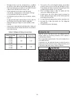
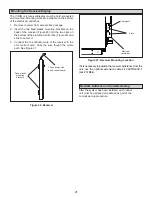
The factory-supplied return air filter is segmented to allow
it to be separated if needed to remove it from the unit in
tight spaces. The segments are connected with hook &
loop (Velcro-style) straps. See Table 1 for filter dimen
-
sions.
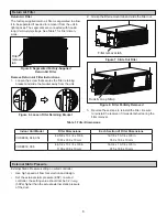
Figure 5. Segmented FactorySupplied
Return Air Filter
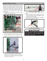
Remove Return Air Filter Instructions
1.
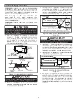
Loosen the screw that secures the filter retaining
bracket and slide the bracket away from the unit.
2.
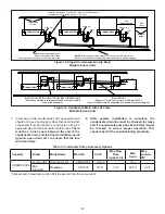
Grasp the filter removal tab and slide the filter out.
Figure 6. Loosen Filter Retaining Bracket
Filter
removal
tab
Figure 7. Slide Out Filter
Filter removal tab
3.
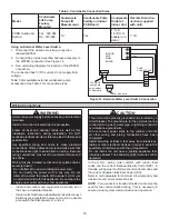
Reverse these steps to reinstall the filter. Be sure
to reinstall the receiver if it was detached during the
filter removal.
Figure 8. Filter Partially Removed
Indoor Unit Model
Filter Dimensions
Each Section of Filter Dimensions
VOSB036, 048, 054
42-5/8 x 13-1/4 x 3/8 in.
1083 x 336 x 10 mm
14-1/8 x 13-1/4 x 3/8 in.
359 x 336 x 10 mm
VOSB072, 096
44-1/2 x 13-1/4 x 3/8 in.
1130 x 336 x 10 mm
14-3/4 x 13-1/4 x 3/8 in.
375 x 336 x 10 mm
Table 1. Filter Dimensions
Hook & Loop Strap
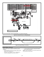
External Static Pressure setting on wired controller
•
Use high speed air flow for selection and design.
•
Set the external static pressure (ESP) on wired
controller, the setting value should not be 0.2 in.w.g
(50Pa) higher than the actual external static pressure
of the duct.
External Static Pressure


