12
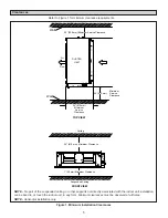
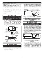
Figure 12. Sloped Condensate Gravity Drain
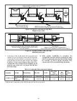
Multiple Indoor Units
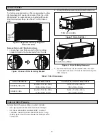
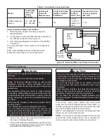
Table 3. Condensate Pump Accessory Options
Capacity
Brand
Model Name
Model #
Cat #
Max Flow
Rate
(gal per hr)
Max
head
Max
suction
lift*
VOSB072-096
Lennox VRF Drain Pump Kit
V8DRNP05
17U32
-
18 in
-
Blue
Diamond
MegaBlue
X87-835
14T71
13.2
66.5 ft
23 ft
*Optional pump maximum suction lift is measured from the pump outlet.
Indoor Unit
2~3-15/16 in.
8 in.
2~3-15/16 in.
2~3-15/16 in.
MAIN DRAIN
INDIVIDUAL DRAIN OUTLET FROM EACH INDOOR UNIT
(Must be connected to internal pump and must be routed to
main drain as shown.)
ti
n
U
r
o
o
d
n
I
ti
n
U
r
o
o
d
n
I
(Sloped at 1/4” per foot (6 mm per 305 mm) AWAY
from unit and should be supported as needed to prevent sagging.)
8 in.
8 in.
Max. 18 in.
Max. 18 in.
Max. 18 in.
Indoor Unit
ti
n
U
r
o
o
d
n
I
ti
n
U
r
o
o
d
n
I
Install a trap for each indoor unit.
3”
3”
Clean Out
3”
3”
3”
3”
Suspension
Rods
3 ft.
(1 m)
Support
straps
NOTE -
Drain line should be sloped 1/4 inch per foot (18 mm per m)
AWAY from unit and should be supported as needed to prevent sagging.
Do not overtighten drain fitting.
Do not operate unit without condensate drain trap.
Install an anti-siphon vent for each trap - must extend above
the height of the coil drain pan by 2” (51 mm).
1 ft.
(305 mm) max
Vent
Vent
Clean Out
Clean Out
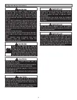
Figure 13. Condensate Drain with Lift Pump
Multiple Indoor Units
7. In all cases, drain should be as short as possible and
should not have any droops or kinks that would restrict
condensate flow and shall be constructed using an
approved pipe. All drains should contain traps.
There
must be a 2inch space between the end of the
condensate drain and the final termination point
(ground, open drain, etc.) to ensure that the line
will drain freely.
8. After system installation is complete, the
condensate drain line must be checked for leaks
and if a condensate pump has been fitted, it must
be checked to ensure proper operation. This
check is part of the commissioning procedure.


