Page 21
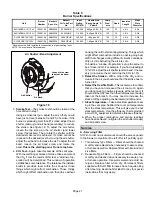
Table 9
Burner Specifications
Unit
Burner
Number
Beckett
Spec. No.
Beckett
Air Tube Part
No.
Input
Rating
BTU/HR
Nozzle Size,
Spray, Angle, &
Pattern
Pump
Pres-
sure
Head
Insertion
Length
Static
Plate
Diameter
SLO183B3/4−101/114V
100591−05
ARM2008
AF46XNHS
101,000
0.65gph X 80° B
140
F3
4−3/4
2−3/4
SLO183B3/4−101/114V
100591−05
ARM2008
AF46XNHS
114,000
*0.65gph X 80° B
140
F3
4−3/4
2−3/4
SLO183B5−135/150V
100591−06
ARM2009
AF46WPHS
135,000
1.00gph x 80°
140
F4
4−3/4
3−3/8
SLO183B5−135/150V
100591−06
ARM2009
AF46WPHS
150,000
*1.00gph X 80° B
140
F4
4−3/4
3−3/8
*Nozzle must be field−installed for conversion to higher heating input.
NOTE − All nozzles are Delavan brand.
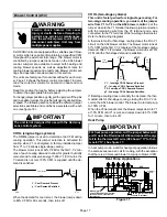
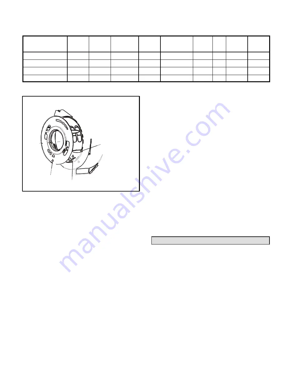
Air Band
(Secondary)
Air Shutter / Band Adjustment
Loosen this screw
to adjust air band.
Air Shutter
Air Band
Figure 19
3.
Smoke Test
The smoke test should be taken at the
hole drilled in step 1.
Using a smoke test gun, adjust the air so that you will
have just a trace (between 0 and #1) of smoke. If the
burner is producing more than #1 smoke, adjust the air
shutter (primary) and air band (secondary) to reduce
the smoke. See figure 19. To adjust the air shutter,
loosen the top screw on the air shutter (and lower
screw, if necessary). Then, rotate the shutter until the
desired smoke level is achieved. If smoke cannot be
reduced to the desired level by moving the air shutter,
adjust the air band to increase the air. To adjust the air
band, loosen the air band screw and rotate the
band.
This is the
starting
point.
Do not stop here.
4.
CO
2
Test
Again, take this sample at the vent pipe.
With the unit firing at a trace of smoke, take a sample of
the CO
2
. From the results of this test, a window of op-
eration" will be determined. This window of operation
establishes some tolerance. The tolerance the installer
builds in provides room within the set-up for those
things which might affect combustion. Those things
which might affect combustion can then do so without
causing the unit to start sooting/smoking. Things which
might affect combustion include a nozzle going bad,
draft that changes during different climatic conditions,
dirty oil, dirt obstructing the air inlet, etc.
To build in a window of operation," set up the burner to
be 2% less in CO
2
. For example, if you find a reading of
12% CO
2
, adjust the air shutter (and air band, if neces-
sary) to increase the air and drop the CO
2
to 10%.
5.
Retest the Smoke
With a drop in the CO
2
and in-
crease in the air you should see that the smoke has re-
turned to 0.
6.
Retest the Overfire Draft
This test serves to confirm
that you have not increased the air too much. Again
you do not want a positive pressure at the test port. It
should still be 0.02 less than the draft pressure reading
taken at the breach. You may need to increase the
stack draft by adjusting the barometric draft control.
7.
Stack Temperature
Take a stack temperature read-
ing in the vent pipe. Subtract the room air temperature
from the stack temperature. This will give you the net
stack temperature. Use the efficiency charts provided
in most CO
2
analyzers to determine furnace efficiency.
8. When the proper combustion and smoke readings
have been achieved, re−tighten the air shutter screw(s)
and air band screw.
Service
A − Servicing Filter
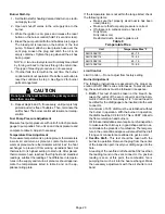
NOTE − Under no circumstances should the access panels
to the blower compartment be left off or left partially open.
1 − Throw-Away Type Filters Filters should be checked
monthly and replaced when necessary to assure prop-
er furnace operation. Replace filters with like kind and
size filters.
2 − Reusable Type Filters Filters should be checked
monthly and cleaned when necessary to assure prop-
er furnace operation. Use warm water and a mild de-
tergent. Replace filter when dry. Permanent filters
supplied with SLO183B furnaces do not require oiling
after cleaning. Examine filter label for any for special
instructions that may apply.


