Page 19
Table 7
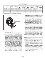
Blower Performance
(0 through 0.50 in. w.g. External Static Pressure Range)
ADJUST"
Jumper
Setting
HEAT" Jumper Speed Position [kBtuh heat input]
COOL" Jumper Speed Position
A
B
C
D
A
B
C
D
cfm
L/s
cfm
L/s
cfm
L/s
cfm
L/s
cfm
L/s
cfm
L/s
cfm
L/s
cfm
L/s
Model SLO183BV101/114V42 Units
Do not use
[−114]
Do not use
[−101]
(+)
N/A
N/A
Same as
NORM
N/A
N/A
Same as
NORM
1610
760
1380
650
1150
540
920
435
NORM
N/A
N/A
1450
684
N/A
N/A
1200
565
1400
660
1200
565
1000
470
800
380
(–)
N/A
N/A
Same as
NORM
N/A
N/A
Same as
NORM
1190
560
1020
480
850
400
680
320
Model SLO183BV135/150V60 Units
Do not use
[−150]
Do not use
[−135]
(+)
N/A
N/A
Same as
NORM
N/A
N/A
Same as
NORM
2300
1085
2070
975
1840
870
1380
650
NORM
N/A
N/A
1730
816
N/A
N/A
1450
684
2000
945
1800
850
1600
755
1200
565
(–)
N/A
N/A
Same as
NORM
N/A
N/A
Same as
NORM
1700
800
1530
720
1360
640
1020
480
NOTE − Continuous Fan air volume is 50% of COOL speed.
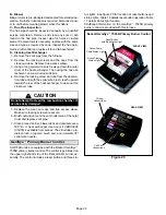
Blower Control (A54)
Figure 18
16−PIN PLUG
(BOARD TO MOTOR)
CFM LED
ADJUST
SELECTOR PINS
(Setting affects
cooling only)
HEATING SPEED
SELECTOR PINS (SEE
TABLE)
COOLING SPEED
SELECTOR PINS
NOTE − The JW1 resistor
must be cut to activate the
HUM terminal.
SLO183B3/4−12
0
SLO183B3/4−10
5
SLO183B5−135
SLO183B5−150
HEAT SPEED PINS
(JUMPERS)
NOTE − Do NOT move
heat speed jumpers from
factory settings.
Start−Up & Adjustment
Before starting unit, make sure the oil tank is adequately
filled with clean No. 1 or No. 2 furnace oil.
NOTE − Water, rust or other contaminants in oil supply sys-
tem will cause malfunction and failure of the internal parts
of the fuel unit.
CAUTION
Never burn garbage or paper in the heating system.
Never leave papers near or around the unit.
CAUTION
Blower access door must be in place before start-up.


