background image

Page 6

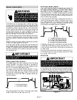
Air from Outside

If air from outside is brought in for combustion and ventila-
tion, the confined space shall be provided with two perma-
nent openings. One opening shall be within 12" (305 mm)
of the top of the enclosure and one within 12" (305 mm) of
the bottom. These openings must communicate directly or
by ducts with the outdoors or spaces (crawl or attic) that
freely communicate with the outdoors or indirectly through
vertical ducts. Each opening shall have a minimum free
area of 1 square inch (6.4 square centimeters) per 4,000
Btu (1172 W) per hour of total input rating of all equipment
in the enclosure. (See figure 4.) When communicating with
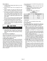
the outdoors through horizontal ducts, each opening shall
have a minimum free area of 1 square inch (6.4 square
centimeters) per 2,000 Btu (586 W) per total input rating of
all equipment in the enclosure (See figure 5).

Ventilation

Louvers

(For unheated

crawl space)

Outlet

Ai

r

Equipment In Confined Space

All Air From Outside

(Inlet Air from Crawl Space and Outlet Air to

Ventilated Attic)

NOTE−The inlet and outlet air openings shall each have a free area of
at least one square inch (6.4 square centimeters) per 4,000 Btu (1172
W) per hour of the total input rating of all equipment in the enclosure.

Ventilation Louvers

(Each End Of Attic)

Water

Heater

Inlet

Air

Chimney or

Oil Vent

Figure 4

Oil

Furnace

When ducts are used, they shall be of the same cross−sec-
tional area as the free area of the openings to which they
connect. The minimum dimension of rectangular air ducts
shall be no less than 3" (76 mm). In calculating free area,
the blocking effect of louvers, grilles, or screens must be
considered. If the design and free area of protective cover-
ing is not known for calculating the size opening required, it
may be assumed that wood louvers will have 20 to 25 per-
cent free area and metal louvers and grilles will have 60 to
75 percent free area. Louvers and grilles must be fixed in
the open position or interlocked with the equipment so that
they are opened automatically during equipment operation.

Equipment In Confined Space

All Air From Outside

Outlet Ai

r

Inlet A

ir

Water

Heate

r

Chimney

Or Oil

Vent

Figure 5

NOTE−Each air duct opening shall have a free area of at least one
square inch (6.4 square centimeters) per 2,000 Btu (586 W) per hour
of the total input rating of all equipment in the enclosure. If the equip-
ment room is located against an outside wall and the air openings
communicate directly with the outdoors, each opening shall have a
free area of at least one square inch (6.4 square centimeters) per
4,000 Btu (1172 W) per hour of the total input rating of all other equip-
ment in the enclosure.

Oil

Furnace

CAUTION

Combustion air openings in the front of the furnace
must be kept free of obstructions. Any obstruction
will cause improper burner operation and may result
in a fire hazard or injury.

CAUTION

The barometric draft control shall be in the same at-
mospheric pressure zone as the combustion air inlet
to the furnace. Deviation from this practice will cause
improper burner operation and may result in a fire
hazard or injury.

Locate & Level the Unit

The compact design of this furnace makes it ideal for a
basement or utility room installation. Choose a central
location for the furnace so that supply air ducts approxi-
mately the same length. This will allow each room to re-
ceive the proper amount of heat. The furnace should be
placed within 10 feet of the chimney, so that the flue con-
nection to the chimney will be of minimum length and have
a minimum number of elbows.

 1 − Set the unit in desired location keeping in mind the

clearances listed in table 2. Also keep in mind oil sup-
ply connections, electrical supply, flue connections
and sufficient clearance for installing and servicing
unit.

Содержание SLO183BF101/114V42

Страница 1: ...O183BV Start Up Performance Check List 2 SLO183BV Unit Parts Arrangement 3 SLO183BV AFG Burner Parts Arrangement 3 Requirements 4 Combustion and Ventilation Air 5 Locate Level Unit 6 Nozzle Adjustment...

Страница 2: ...1334 27 686 18 x 21 457 x 533 18 x 16 457 x 406 SLO183BF135 150V60 22 1 2 572 37 940 52 1 2 1334 27 686 21 x 21 533 x 533 21 x 16 533 x 406 SLO183BR135 150V60 22 1 2 572 37 940 52 1 2 1334 27 686 21 x...

Страница 3: ...eat Exchanger Blower Control A54 Not Visible Located on blower housing Clean Out Port SLO183BV AFG Burner Parts Arrangement ESCUTCHEON PLATE MAIN HOUSING HEAT SHIELD BURNER CONTROL with Reset Button O...

Страница 4: ...is strongly recommended especially in new homes Refer to table 1 or the unit plate for specific combus tion air opening dimensions Table 1 Combustion Air Opening Dimensions Model No Combustion Air Ope...

Страница 5: ...a basement or large equipment room with a volume greater than 50 cubic feet 1 4 cubic meters per 1 000 Btu 293 W per hour of the combined input rating of all appliances installed in that space This s...

Страница 6: ...rs will have 20 to 25 per cent free area and metal louvers and grilles will have 60 to 75 percent free area Louvers and grilles must be fixed in the open position or interlocked with the equipment so...

Страница 7: ...114 and 150 units Inspect the spark transformer leads also to en sure they are still attached to the electrodes The burner assembly is attached to the vestibule panel by three nuts Slots are provided...

Страница 8: ...rd ing to the requirements of the National Fire Protection Asso ciation The smallest dimensions of the chimney should be at least equal to the diameter of the furnace vent connector Make sure the chim...

Страница 9: ...not be less than the area of the largest vent or vent connection plus 50 of the area of the additional vent or vent con nection Chimney must be able to sufficiently vent all appliances operating at th...

Страница 10: ...hting instruction on the unit place the appliance being inspected in operation Adjust ther mostat so appliance will operate continuously 5 Test for spillage using a draft gauge 6 After it has been det...

Страница 11: ...edures that should be followed when installing the supply air plenum 1 Use sealing strips of fiberglass 2 In all cases the plenum should be secured to furnace or evaporator cabinet with sheet metal sc...

Страница 12: ...ings IMPORTANT Both oil supply and return pipes must be submerged in oil in the supply tank Table 4 Two Pipe Maximum Pipe Length H R Lift H 3450 RPM 3 GPH 11 4 LPH 3 8 10 mm OD Tubing 1 2 12 mm OD Tub...

Страница 13: ...een the tank shut off valve and the burner Locate filter close to but at least 3 feet away from the burn er for easy maintenance Table 6 lists the filters for the SLO183B furnace Consult the burner ma...

Страница 14: ...hrough specified high voltage opening Do not com bine voltage in one opening CAUTION Use copper conductors only IMPORTANT If using a programmable thermostat be sure to use a type of thermostat that re...

Страница 15: ...ams 1 Heat 1 Cool ComfortSense 7000 L7724U 1 Heat 2 Cool ComfortSense 7000 L7724U 1 Heat 1 Cool ComfortSense 7000 L7724U with Thermostat Dehumidification Mode 1 Heat 2 Cool ComfortSense 7000 L7724U wi...

Страница 16: ...age Heat Pump ComfortSense 7000 L7724U with Dual Fuel Control Mode Dual Fuel Two Stage Heat Pump ComfortSense 7000 L7724U with Dual Fuel Control Mode Dual Fuel Two Stage Heat Pump ComfortSense 7000 L7...

Страница 17: ...de mand is satisfied OFF CALL 100 82 Y 60 sec 7 5 minutes 82 y Y Cool Demand Present y Cool Demand Satisfied When the demand for cool is met the blower ramps down to 82 CFM for 60 seconds then turns...

Страница 18: ...times the light may appear to flicker or glow This takes place when the control is communicating with the motor be tween cycles This is normal operation After the CFM for each application has been de...

Страница 19: ...1600 755 1200 565 N A N A Same as NORM N A N A Same as NORM 1700 800 1530 720 1360 640 1020 480 NOTE Continuous Fan air volume is 50 of COOL speed Blower Control A54 Figure 18 16 PIN PLUG BOARD TO MOT...

Страница 20: ...n tempera tures in the supply and return air plenums should approxi mate the temperatures listed in table 8 and on the ap pliance rating plate If the temperature rise is not within the range listed ch...

Страница 21: ...hings which might affect combustion Those things which might affect combustion can then do so without causing the unit to start sooting smoking Things which might affect combustion include a nozzle go...

Страница 22: ...rossover tube CAUTION Do not attempt to clean the combustion chamber It can be easily damaged 5 Replace the clean out caps and flue access elbow Make sure locking screws are secure 6 Brush out and vac...

Страница 23: ...f as long as the button is held Enables pump priming After the reset button has been held for 15 seconds The button can then be clicked during the next ignition sequence to enter pump prime mode Run i...

Страница 24: ...oft lockout reset oil primary control allows second ignition attempt Primary control enters hard lockout after second ignition failure 15 sec onds without flame being sensed Push reset but ton on prim...

Страница 25: ...speed ramps down Circulat ing fan shuts off after 60 seconds Thermostat begins call for fan G terminal is energized Indoor blower is energized immediately at 50 of cool speed ST9103A may be factory co...

Страница 26: ...ect the flame detector wires at the primary control If the burner starts fault is in the detector circuit Flame detector leads are shorted Separate leads Flame detector exposed to light Seal off false...

Страница 27: ...from unit Inspect the nozzle for plugged orifice or carbon build up around orifice Nozzle orifice plugged Replace nozzle with the same size spray angle and spray pattern Nozzle strainer plugged Poor o...

Страница 28: ...ter burner fires immedi ately jumper across flame detector termi nals at the pri mary control If burner con tinues to run does not lock out of safety fault may be due to poor fire Inspect fire Unbalan...

Страница 29: ...wheel dirty Clean blower wheel Wrong motor rotation Replace motor Restrictions in return or supply air system Correct cause of restriction Power If voltage fluctuates fault is in the power source Rech...

Страница 30: ...ed heat exchanger Clean heat exchanger Readjust burner Insufficient overfire draft Increase draft Incorrect nozzle assembly depth Set to 1 13 Too little combustion air Increase combustion air High sta...

Отзывы: