Page 18
2-
Burner Flame
-- Start burner and allow to operate for
a few minutes to establish normal burning conditions.
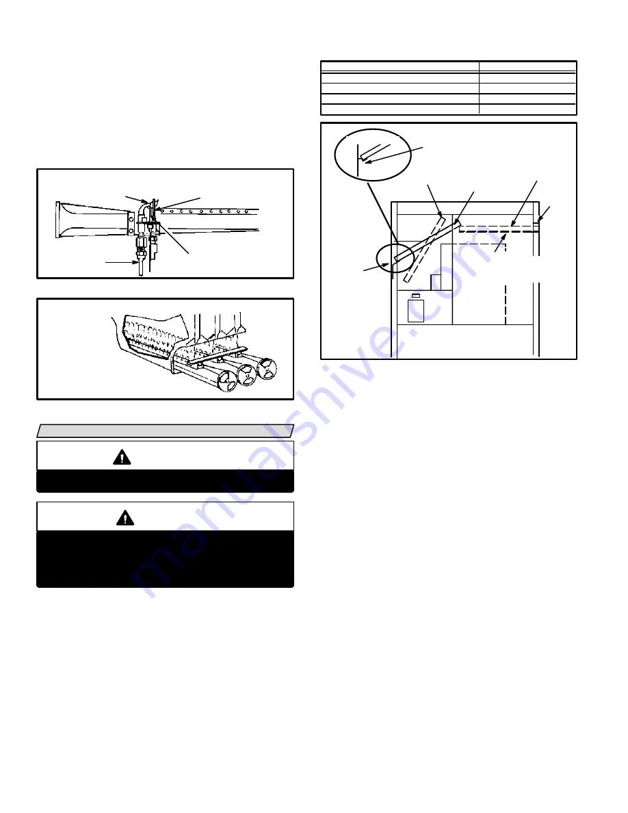
Check burner flame by observation. Flame should be
predominantly blue in color, strong in appearance
and should rise directly from the burner ports in the
heat exchanger. Check to see that flame is burning
from all continuous ribbon ports and that flame does
not impinge on the sides of the heat exchanger. Refer
to figure 26.
PILOT FLAME
(Side View)
BURNER
PILOT GAS
LINE
ELECTRODE
FIGURE 25
FLAME SENSOR
FLAME SHOULD
ENGULF UPPER
1/3 OF FLAME SENSOR
BURNER FLAME
FIGURE 26
NOTE-VIEW BURNER FLAME THROUGH
DAMPER OPENING (Not Shown)
SERVICE
WARNING
Disconnect power before servicing unit.
CAUTION
Label all wires prior to disconnection when servicĆ
ing controls. Wiring errors can cause improper
and dangerous operation. Verify proper operation
after servicing.
At the beginning of each heating season, the system
should be checked as follows:
Blower
Check and clean blower wheel for any debris. Blower
motor is prelubricated for extended bearing life. No
further lubrication is needed.
Filters
G20R series units are equipped with two permanent inĆ
ternal filters which should be inspected monthly and
cleaned when necessary to assure proper furnace opĆ
eration. See table 5 for filter sizes. Use the following
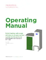
procedure and figure 27 to clean filter.
TABLE 5
MODEL NO.
FILTER SIZE
Q2/3-50, Q3-75
Q4-75, Q3/4-100
Q5-100, Q3-125, Q4/5-125
20 X 10 X 1
20 X 12 X 1
20 X 14 X 1
Q4/5-150
20 X 16 X 1
FIGURE 27
BLOWER
RIGHT
FILTER
LEFT FILTER
LEFT
SUPPORT
ANGLE
RIGHT FILTER
SUPPORT ANGLE
(ON THREE SIDES)
-150 UNITS
MAKE SURE FILTER IS PLACED
INTO THIS CHANNEL
-150 UNITS
ROTATE FILTER
TO REMOVE
TAB
1- Turn off electric power to furnace.
2- Remove upper access panel.
3- Remove blower access panel.
4- Lift left side filter over left support angle. For easy hanĆ
dling, hold filter at center bottom.
5- Rotate filter sideways and pull it through the blower
access panel opening.
6- Pull the second filter out the same way as the first.
7- Wash filters with warm water and mild detergent.
When dry, filters should be sprayed with filter handiĆ
coater before replacing. Filter Handicoater is RP prodĆ
ucts coating no. 418 and is available as Lennox part
no. P-8-5069.
8-Right filter should be under tab of right filter support angle.
9-Left filter must rest against top edge of right filter.
Flue and Chimney
Check flue pipe, chimney and all connections for tightĆ
ness and to make sure there is no blockage.
Cleaning Heat Exchanger and Burners
NOTE-Use papers or protective covering in front of furĆ
nace while cleaning furnace.
To clean heat exchanger:
1- Turn off both electrical and gas power supplies to furĆ
nace. Refer to figures 1 and 2 during disassembly and
reassembly procedures.
2- Remove burner and upper access panel, flue pipe
and draft hood.
Содержание G20R series
Страница 14: ...Page 14 FIGURE 17 TYPICAL G20R WIRING DIAGRAM ...


