Page 12
Leak Check
After gas piping is completed, carefully check all piping
connections (factory and field) for gas leaks. Use a leak
detecting solution or other preferred means.
CAUTION
Some soaps used for leak detection are corrosive
to certain metals. Carefully rinse piping thoroughly
after leak test has been completed. Do not use
matches, candles, flame or other sources of igniĆ
tion to check for gas leaks.
NOTE-In case emergency shutdown is required, shut
down main manual gas valve and disconnect main
power to unit. These devices should be properly laĆ
beled by the installer.
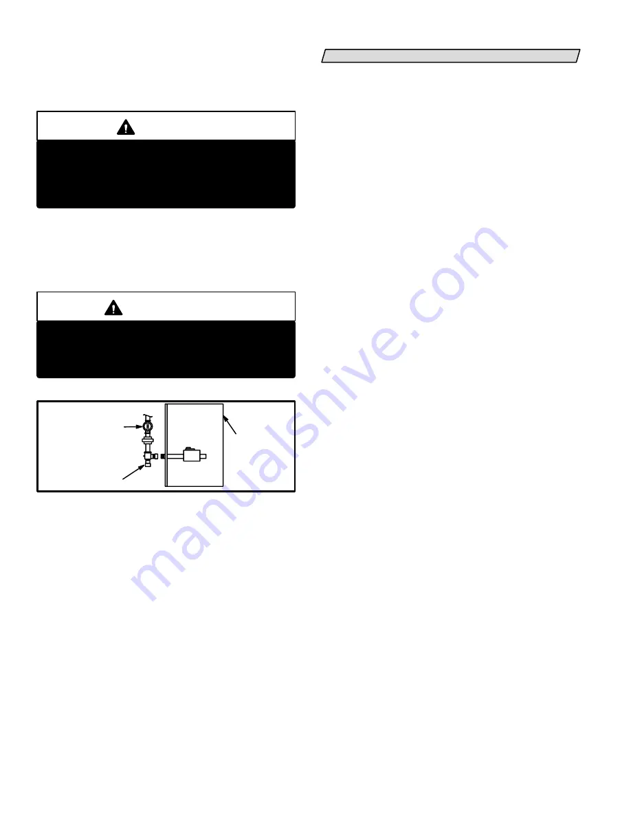
IMPORTANT
When testing pressure of gas lines, gas valve must
be disconnected and isolated. See figure 13. Gas
valves can be damaged if subjected to more than
1/2 psig (3.48 kPa).
FIGURE 13
MANUAL MAIN
SHUT-OFF VALVE
WILL NOT HOLD
NORMAL TEST
PRESSURE
CAP
ISOLATE
GAS VALVE
FURNACE
The furnace must be isolated from the gas supply sysĆ
tem by closing its individual manual shut-off valve durĆ
ing any pressure testing of the gas supply system at
pressures equal to or less than 1/2 psig (3.48 kPa).
G20RXE Series Units
IMPORTANT-G20RXE series units (units equipped with
flame rods) are approved for use with natural gas only.
ELECTRICAL
Refer to figure 14 for thermostat wiring, figure 15 for
BCC location, figure 16 for pointĆtoĆpoint field wiring,
and figure 17 for schematic wiring diagram and troubleĆ
shooting.
1- Select fuse and wire size according to motor amps.
2- Snaphole plugs are provided on both sides of cabinet
to facilitate wiring.
3- Install room thermostat according to instructions proĆ
vided with thermostat.
4- Install a separate fused disconnect switch near the
unit so power can be turned off for servicing.
5- Route thermostat wire as shown in figure 14. Keep
wire away from draft hood and flue pipe. Do not route
wire across draft hood.
6- Complete wiring connections to equipment using wiring
diagrams provided with unit and in figures 15, 16 and 17.
Use 18 gauge wire or larger for thermostat connections.
7- Electrically ground unit in accordance with local codes
or, in the absence of local codes, in accordance with the
current National Electric Code (ANSI/NFPA No. 70) and
in Canada with the current Canadian Electric Code part
1 (CSA standard C22.1).
8- A 120 volt accessory terminal (ACC) is provided on
the BCC blower control center. Any accessory rated
up to 1 amp can be connected to this terminal and the
neutral leg of the accessory can be attached to any
free 120 volt neutral terminal on the BCC blower conĆ
trol center. The accessory terminal is energized whenĆ
ever the blower is in operation. See figure 15 . A trouĆ
bleshooting flowchart for the BCC blower control is
located at the end of this manual.
9- The continuous fan (CF) 120 volt terminal is used with
an optional continuous low fan kit that is available
from Lennox. The kit allows the furnace blower to run
continuously on low speed.
10- Check the thermostat selector jumper on the BCC
board. The jumper is factoryĆpositioned for use
with a mechanical thermostat.
This jumper must
be repositioned if an electronic thermostat will be
used in the application.
Содержание G20R series
Страница 14: ...Page 14 FIGURE 17 TYPICAL G20R WIRING DIAGRAM ...


