Page 17
90
270
150
210
90
150
270
210
90
270
150
210
90
270
150
210
90
270
150
210
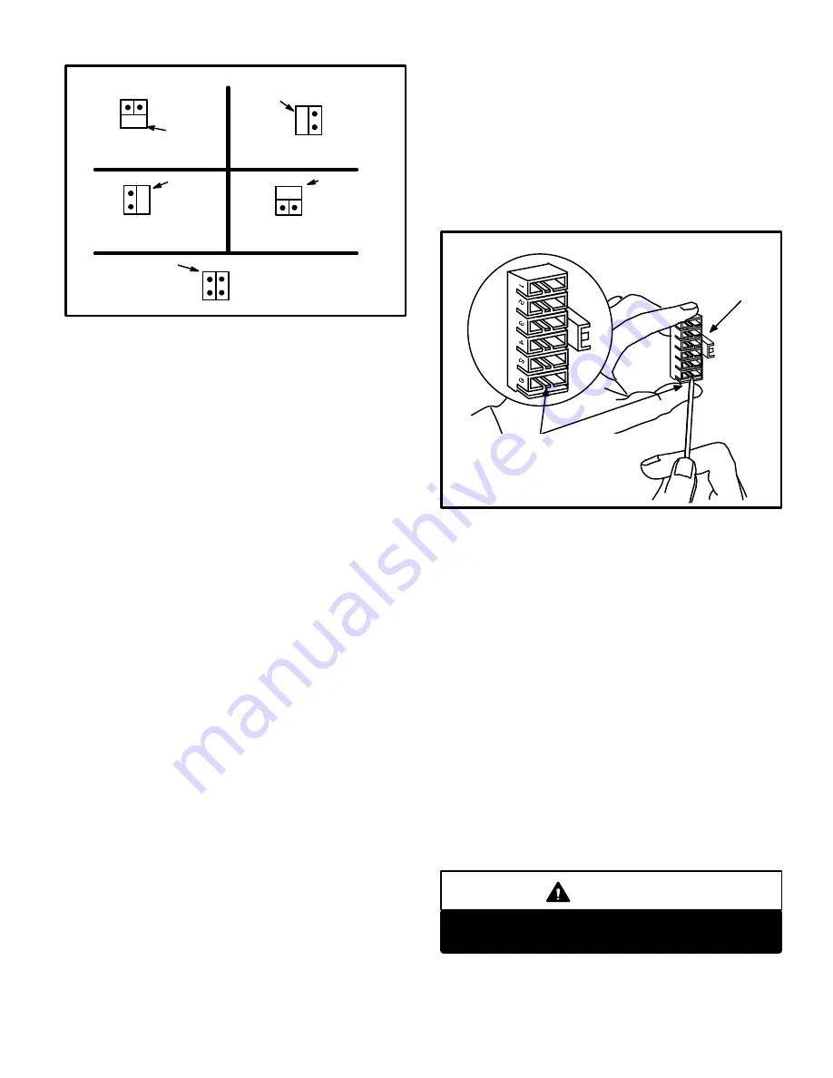
JUMPER
JUMPER
JUMPER
JUMPER
NO JUMPER
90 SECOND FAN
OFF TIME
150 SECOND FAN
OFF TIME
210 SECOND FAN
OFF TIME
270 SECOND FAN
OFF TIME
330 SECOND FAN
OFF TIME
FIGURE 23
FAN OFF TIME ADJUSTMENT
Temperature Rise
Check temperature rise and, if necessary, adjust blowĆ
er speed to maintain temperature rise within range
shown on unit rating plate.
Thermostat Selector Jumper
Check the thermostat selector jumper on the BCC
board. The jumper is factoryĆpositioned for use with a
mechanical thermostat.
This jumper must be reposiĆ
tioned if an electronic thermostat will be used in the apĆ
plication.
Thermostat Adjustment
Thermostat anticipator setting (if adjustable) should be
set according to amps listed on wiring diagram on unit.
Electrical
1- Check all wiring for loose connections.
2- Check for correct voltage at unit (unit operating).
3- Check amp-draw on blower motor.
Motor Nameplate__________Actual__________
Flue and Chimney
1- Check flue pipe, chimney and all connections for
tightness and to make sure there is no blockage.
2- Check unit for proper draft.
Blower Speeds
Blower speed tap selection is accomplished by changing
the taps at the harness connector at the blower motor.
Disconnect harness connector from motor to expose
speed selectors. See figure 24 and unit wiring diagram.
1- Turn off electrical power to furnace.
2- Remove filter access panel.
3- Lift left side filter over left support angle. For easy hanĆ
dling, hold filter at center bottom.
4- Rotate filter sideways and pull it through the blower
access panel opening.
5- Grasp blower motor harness connector located on
back on motor. Depress lock tab and pull connector
from motor.
6- Pull harness connector and wires through blower acĆ
cess panel opening.
7- Select desired taps for heating and cooling. (White =
common, Red = heating, Black = cooling)
8- Depress harness connector tab to release wire termiĆ
nal. Select connector location for new speed (refer to
unit wiring diagram). Insert wire terminal until it is seĆ
curely in place. See figure 24.
9- Replace harness connector to motor until it is securely
in place.
FIGURE 24
BLOWER SPEED TAP SELECTION
HARNESS
CONNECTOR
DEPRESS TAB TO RELEASE
WIRE TERMINAL. SELECT CONĆ
NECTOR LOCATION FOR NEW
SPEED (REFER TO UNIT WIRING
DIAGRAM). INSERT WIRE UNTIL
IT IS SECURELY IN PLACE.
Failure to Operate
If unit fails to operate check the following:
1- Is thermostat calling for heat?
2- Is main disconnect switch closed?
3- Is there a blown fuse?
4- Is filter dirty or plugged? Dirty or plugged filters will
cause unit to go off on limit control.
5- Is gas turned on at meter?
6- Is manual main shut-off valve open?
7- Is internal manual shut-off valve open?
After items 1 through 7 have been checked and unit still
will not start, manually reset vent safety shut-off switch
located at the right side of draft hood. If unit operation reĆ
sumes and then cuts out again, inspect furnace vent sysĆ
tem for proper sizing and installation. Also, check for
vent blockage and for proper draft. If unit still does not
start, reset roll-out switch on burner box. See figure 27. If
unit starts and cuts out, check heat section for blockage.
Pilot and Burner Flame
CAUTION
Check pilot flame and burner flame periodically to
ensure proper operation.
1-
Pilot Flame
-- Pilot flame must surround the end of
flame sensor for proper operation of pilot safety cirĆ
cuit. See figure 25.
Содержание G20R series
Страница 14: ...Page 14 FIGURE 17 TYPICAL G20R WIRING DIAGRAM ...


