62
Staking a Road Alignment
General Guide to RoadPlus - 4.0.0en
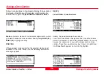
Orient -
Select a method of orientation as reference direction.
The next line shows the station of the horizontal alignment to
which the cross section is assigned. The number and letter
in brackets to the right express how many positions left (L) or
right (R) of the cross section's centre line you are working or if
you are on the centre (C). A * next to it indicates that this point
has been staked already.
Out / In and Right / Left -
This is the range to the selected
point and is updated as the antenna pole is moved.
Cut / Fill -
Indicates the cut / fill to the surface. If the point
elevation in the previous panel has been changed, the value
for cut applies to this new elevation.
Once in the Stakeout graphics screen navigate to the correct
point as normal. Place the antenna pole at the location. Be
sure that the antenna is levelled. Once the desired point is
located:
OCUPY (F1)
The current
Point ID
may be accepted or changed.
3D Quality -
Observe the position quality indicator. Data
should not be recorded until you are satisfied with this value.
When you are satisfied:
STOP (F1)
Panel STAKE-OUT \ Occupy Point
DIFF (F2)


