background image

Digital Stepper Drive DM320T

10

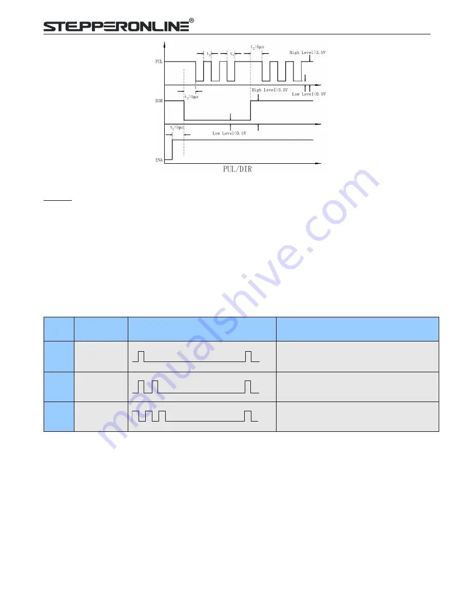
Figure 10: Sequence chart of control signals

Remark:

a) t1: ENA must be ahead of DIR by at least 5

s. Usually, ENA+ and ENA- are NC (not connected). See

“Connector P1 Configurations” for more information.

b) t2: DIR must be ahead of PUL effective edge by 5

s to ensure correct direction;

c) t3: Pulse width not less than 7.5

s;

d) t4: Low level width not less than 7.5

s.

11. Protection Functions

To improve reliability, the drive incorporates some built-in protections features.

Priority

Time(s) of

Blink

Sequence wave of red LED

Description

1st

1

Over-current protection activated when peak
current exceeds the limit.

2nd

2

Over-voltage protection activated when drive
working voltage is greater than 34VDC

3nd

3

Reserved.

When above protections are active, the motor shaft will be free or the red LED blinks. Reset the drive by repowering it
to make it function properly after removing above problems.

Содержание STEPPERONLINE DM320T

Страница 1: ...User Manual DM320T 2 Phase Digital Stepper Drive 7 Zhongke Road Jiangning Nanjing China T 0086 2587156578 Web site www omc stepperonline com E Mail sales stepperonline com ...

Страница 2: ...2 Connections of 6 lead Motor 5 5 2 1 Half Coil Configuration 5 5 2 2 Full Coil Configuration 5 5 3 Connections of 8 lead Motor 6 5 3 1 Series Connection 6 5 3 2 Parallel Connection 6 6 Power Supply Selection 6 6 1 Regulated or Unregulated Power Supply 7 6 2 Power Supply Sharing 7 6 3 Selecting Supply Voltage 7 7 DIP Switch Configurations 7 7 1 Microstep Resolution Configurations 7 7 2 Current Con...

Страница 3: ... inputs Input voltage 18 30VDC 8 selectable micro step resolutions of 400 12800 via DIP switches 8 selectable output current settings of 0 3 2 2A via DIP switches Soft start with no jump when powered on Pulse input frequency up to 60 KHz Automatic idle current reduction Protections for over voltage and over current 1 2 Applications The DM320T stepper drive are designed to power 2 phase 1 8 or 4 ph...

Страница 4: ...C 50 C 32 F 122 F Vibration 10 50Hz 0 15mm Storage Temperature 20 C 65 C 4 F 149 F Weight Approx 90g 3 5 oz 2 3 Mechanical Specifications unit mm 1inch 25 4mm Figure 1 Mechanical specifications Side mounting recommended for better heat dissipation 2 4 Elimination of Heat DM320T reliable working temperature should be 60 140 F It is recommended to mount the drive vertically to maximize heat sink are...

Страница 5: ...swapping the connection of two wires of a coil e g A and A to the drive will reverse motor direction OPTO Opto coupler power supply and the typical voltage is 5V Series connect resistors at the PUL DIR ENA terminals for current limiting when 12V or 24V used ENA Enable signal This signal is used for enabling disabling the drive High level 5V NPN control signal for enabling the drive and low level f...

Страница 6: ... for detail 4 Control Signal Connector P1 Interface The DM320T can accept differential and single ended inputs including open collector and PNP output The DM320T has 3 optically isolated logic inputs which are located on connector P1 to accept line drive control signals These inputs are isolated to minimize or eliminate electrical noises coupled with the drive control signals Recommend using line ...

Страница 7: ...ings The higher torque configuration or full coil uses the full coil windings 5 2 1 Half Coil Configuration As previously stated the half coil configuration uses 50 of the motor phase windings This gives lower inductance hence lower torque output Like the parallel connection of 8 lead motor the torque output will be more stable at higher speeds This configuration is also referred to as half choppe...

Страница 8: ...ed current to prevent overheating Figure 7 8 lead motor series connections 5 3 2 Parallel Connection An 8 lead motor in a parallel configuration offers a more stable but lower torque at lower speeds But because of the lower inductance there will be higher torque at higher speeds Multiply the phase or unipolar current rating by 1 96 or the bipolar current rating by 1 4 to determine the peak output ...

Страница 9: ...siderably less than motor current For example two 3A motors can be well supplied by one power supply of 4A rating 6 2 Power Supply Sharing Multiple DM320T drives can share one power supply to reduce cost if that power supply has enough power capacity To avoid cross interference connect each stepper drive directly to the shared power supply separately To avoid cross interference DO NOT daisy chain ...

Страница 10: ...however the selection also depends on leads and connections The first three bits SW1 2 3 of the DIP switch are used to set the dynamic current Select a setting closest to your motor s required current 7 2 1 Dynamic Current Configurations Peak Current RMS Current SW1 SW2 SW3 0 3A 0 21A ON ON ON 0 5A 0 35A OFF ON ON 0 7A 0 49A ON OFF ON 1 0A 0 71A OFF OFF ON 1 3A 0 92A ON ON OFF 1 6A 1 13A OFF ON OF...

Страница 11: ...arately connecting the drives to the power supply is recommended instead of daisy chaining It is prohibited to pull and plug connector P2 while the drive is powered ON because there is high current flowing through motor coils even when motor is at standstill Pulling or plugging connector P2 with power on will cause extremely high back EMF voltage surge which may damage the drive 9 Typical Connecti...

Страница 12: ...vel width not less than 7 5 s 11 Protection Functions To improve reliability the drive incorporates some built in protections features Priority Time s of Blink Sequence wave of red LED Description 1st 1 Over current protection activated when peak current exceeds the limit 2nd 2 Over voltage protection activated when drive working voltage is greater than 34VDC 3nd 3 Reserved When above protections ...

Страница 13: ...traced to electrical noise controller software errors or mistake in wiring Problem Symptoms and Possible Causes Symptoms Possible Problems Motor is not rotating No power Microstep resolution setting is wrong DIP switch current setting is wrong Fault condition exists The drive is disabled Motor rotates in the wrong direction Motor phases may be connected in reverse The drive in fault DIP switch cur...

Отзывы: