Hardware
installation manual of the multi-axis drive MX4660
Leadshine Technology Co., Ltd
Leadshine America, Inc.
Page 14/28
3/F, Block 2, Nanyou Tianan Industrial Park, Shenzhen, China
25 Mauchly, Suite 318, Irvine, CA 92618, USA
Tel: 86-755-26409254
Fax: 86-755-26402718
Tel: 1-949-608-7270
Fax: 1-949-608-7298
Web:
www.leadshine.com
Email:
Web:
www.leadshine.com
Email:
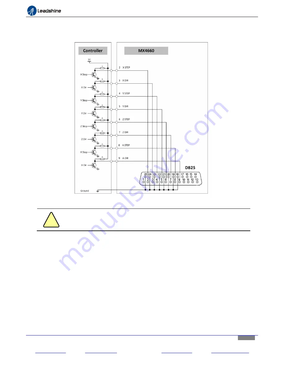
Step and direction signal voltage should be 3.3-5 VDC and “Active High”. In the controller configuration, the step
width should be configured to a value at least 2.5 μS, and direction setup time needs to be at least 4 uS.
Otherwise, it could cause loss of steps, or no motion at all for the controlled stepper motors.
Figure 13
Connecting the step & direction signals of a controller to the MX4660
!
Caution
If step & direction signal voltage is lower than 5 VDC, you may need to increase step
width and direction setup time (> 4 uS) to move your motors, or avoid loss of step.
Connecting the DB25 Fault Output Pin
The fault pin connection is optional.
The MX4660 4-Axis stepper drive will send a “Fault” output signal of 5 VDC
back to the controller via Pin 15 (Appendix A) of the DB25 connector, in one of the following scenario:
Any of the 4 stepper drive module is in protection mode including over voltage and over current. Read
“Protection” detail in the MX4660 datasheet.
The connected external E-Stop switch in the digital input is pressed.
With the receiving of a fault received from the MX4660, a controller can be notified an abnormal event has
happened. It can then react, such as shutting down the whole control machine/device for machine damage.
Connecting the DB 25 Charge Pump Pin
The charge pump pin connection is optional.
To implement the “Charge Pump” feature of the MX4660 4-Axis


