Hardware
installation manual of the multi-axis drive MX4660
Leadshine Technology Co., Ltd
Leadshine America, Inc.
Page 12/28
3/F, Block 2, Nanyou Tianan Industrial Park, Shenzhen, China
25 Mauchly, Suite 318, Irvine, CA 92618, USA
Tel: 86-755-26409254
Fax: 86-755-26402718
Tel: 1-949-608-7270
Fax: 1-949-608-7298
Web:
www.leadshine.com
Email:
Web:
www.leadshine.com
Email:
By default, the charge pump feature is turned on, with the “Charge Pump” set to the “OFF” position (means
“Charge Pump” ON). To disable this feature and make MX4660 to work with control systems (e.g. PLC, motion
controller, etc.) not designed to use the “Charge Pump” feature, set the “Charge Pump” to “ON” position
(meaning “Charge Pump” OFF).
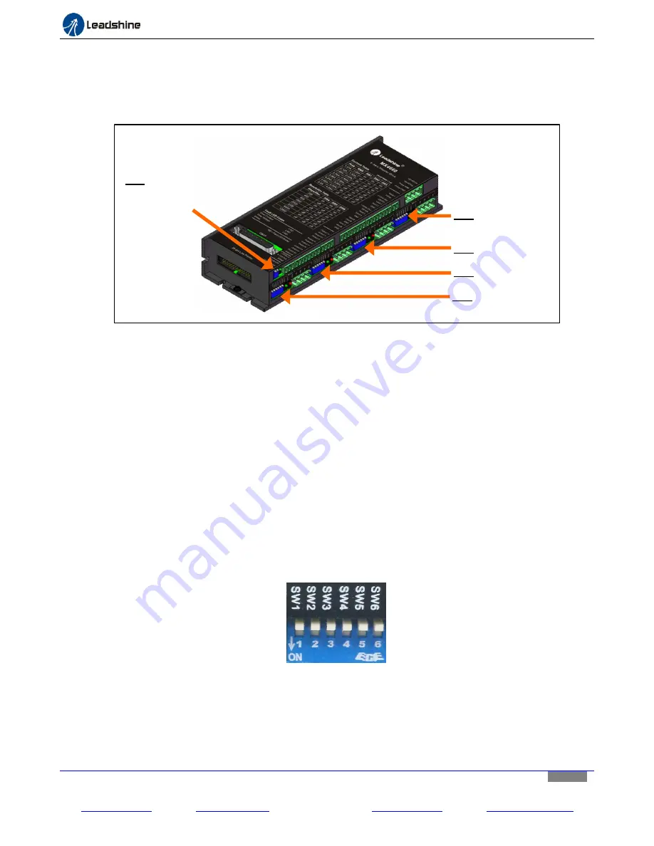
Figure11
MX4660 DIP switch locations
Setting the “Smoother” Switch
The firmware of each of the four stepper drive modules in the MX4660 adopts a feature called “smoothing” to
smooth input step signals. When an input pulse emulated by the connected motion controller or CNC control
system are not in linear or equivalent width, called “noise pulse”, it will cause erratic motion and additional
motor/drive noise. Turning on the built-in digital smoother will trigger the input pulse train smoothing and could
potentially improve motion performance such as less jittering, higher torque, and quicker response. Because of
the complexity for different machines/devices, the “Smoother” feature may or may not have obvious effect (but
at least no hurt for the bottom line). Turning on this switch or off is totally your choice. By default, the MX4660
smoother is set to off.
Configuring Output Current and Micro Step
The MX4660 allows individual settings of the output current and micro step resolution for each stepper motor,
via the 6-pin DIP switches of four stepper drive modules (DP1, DP2, DP3 and DP4 on Figure 11).
Figure 12
DIP switch for current & micro step configurations
Configuring Output Current
The output current configuration is required.
Use SW1, SW2, and SW3 of the 6-pin DIP switch (Figure 12) of a
stepper drive module to configure the output current to the driven stepper motor. Refer to Table 1 for available
output current settings.
DP5: Charge Pump switch&
Smoother switch
DP3: Z axis DIP switch
DP2: Y axis DIP switch
DP1: X axis DIP switch
DP4: A axis DIP switch


