32
ELD2-RS70** User Manual
Setup
value
selection 1 of
internal command
speed(INTSPD1)
selection 2 of internal
command speed
(INTSPD2)
selection 3 of
internal command
speed (INTSPD3)
selection of
Speed
command
1
OFF
OFF
NO effect
1st speed
ON
OFF
2nd speed
OFF
ON
3rd speed
ON
ON
4th speed
2
OFF
OFF
NO effect
1st speed
ON
OFF
2nd speed
OFF
ON
3rd speed
ON
ON
Analog speed
command
3
The same as [Pr3.00=1]
OFF
1st to 4th
speed
OFF
OFF
ON
5th speed
ON
OFF
ON
6th speed
OFF
ON
ON
7th speed
Pr3.01
Speed command rotational
direction selection
Range
unit
default
Related
control mode
0 -1
-
0
S
Select the Positive /Negative direction specifying method
Setup
value
Select speed command sign
(1st to 8th speed)
Speed command direction
(VC-SIGN)
Position command
direction
0
+
No effect
Positive direction
-
No effect
Negative direction
1
Sign has no effect
OFF
Positive direction
Sign has no effect
ON
Negative direction
Pr3.02
Input gain of speed command
Range
unit
default
Related
control mode
10 -2000
(r/min)/v
500
S T
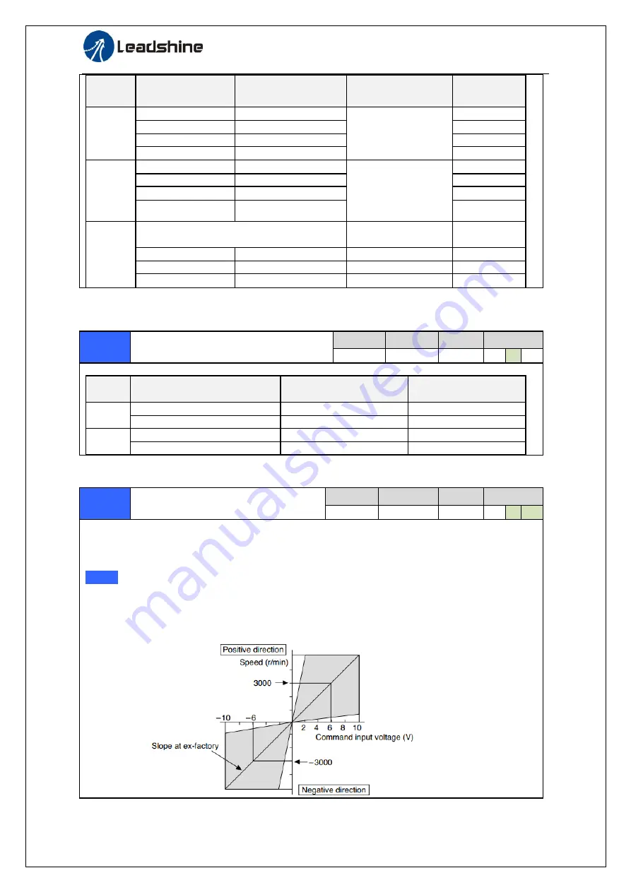
Based on the voltage applied to the analog speed command (SPR), set up the conversion gain to
motor command speed.
You can set up “slope” of relation between the command input voltage and motor speed, with Pr3.02.
Default is set to Pr3.02=500(r/min)/V, hence input of 6V becomes 3000r/min.
Notice:
1. Do not apply more than ±10V to the speed command input(SPR).
2. When you compose a position loop outside of the driver while you use the driver in velocity
control mode, the setup of Pr3.02 gives larger variance to the overall servo system.
3. Pay an extra attention to oscillation caused by larger setup of Pr3.02.


