Hardware Manual for the DMC5400 Motion Controller
Tel: +086 0755-26434369 Email: [email protected] Web Site: www.leadshine.com
Page: 7/36
55
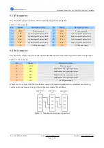
PUL2+ J5: short circuit between pin1 and pin2 J5: short circuit between pin2 and pin3
57
DIR2+ J6: short circuit between pin1 and pin2 J6: short circuit between pin2 and pin3
Pin Number of X2
Signal
Differential Output
Single-ended (Open collector) output
1
PUL3+ J7: short circuit between pin1 and pin2 J7: short circuit between pin2 and pin3
3
DIR3+ J8: short circuit between pin1 and pin2 J8: short circuit between pin2 and pin3
Note:
Differential signals are preferred due to their excellent noise immunity. Recommend use differential output
if possible.
2.4.2 Choosing External or Internal Power Supply (J9~J10)
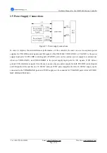
J9 and J10 on the DMC5400 are used for choosing external or internal power supply for the card. Choosing
external power supply for the card can offer higher noise immunity performances and full functions of the card.
While choosing internal power supply is easier for the user to set up the system (no external power supply is
needed.), but with lower noise immunity performances and no I/O functions. Here we recommend the user
choosing external power supply for the card. The default mode is choosing external power supply for the card, see
Figure2.3.
Figure 2.3: J9~J10 jumpers
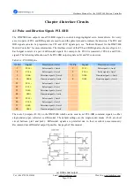
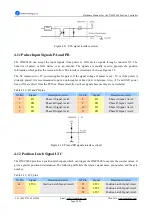
2.4.3 Emergency Stop Input Signal Setting (J11)
J11 on the DMC5400 is specially used for setting effective logic level of the emergency stop signal. Jumper
settings and their relative effective logic levels are shown in the Table 2-2. The default setting of the J11 is pin1
and pin2 short circuit, namely the emergency stop signal is effective when it is pulled to low level. Please check
the input signal and the setting of emergency stop signal when the DMC5400 can not operate properly.
Table 2-2: Emergency stop input signal setting
Effective Level
J11 Settings
Low (EMG and EXGND is in conducting state.)
Pin 1 and pin2 short circuit
High (EMG and EXGND is in disconnection state.)
Pin 2 and pin3 short circuit
Figure 2.4: J11 jumper


