Hardware Manual for the DMC5400 Motion Controller
Tel: +086 0755-26434369 Email: [email protected] Web Site: www.leadshine.com
Page: 12/36
Chapter 4 Interface Circuits
4.1 Pulse and Direction Signals PUL/DIR
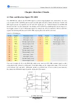
The DMC5400 can output 4 axes PUL/DIR signals to control 4 stepping/digital servo motor drivers. For every
axis, two pairs of PUL and DIR signals are used to send the pulse train and to indicate the direction. The PUL and
DIR signals can also be programmed as CW and CCW signals pair, see
“
Software Manual for the DMC5400
Motion Controller
”
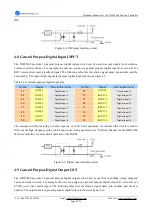
for more information. The interface circuit of the PUL and DIR signals is shown as figure 4.1.
Each signal consists of a pair of differential signals. For example, the PUL0 is consisted of PUL0+ and PUL0-
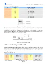
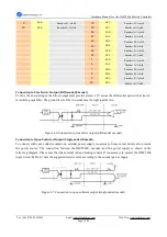
signals. The following table shows all the PUL/DIR output signals on X1 and X2 connectors.
Table 4-1: PUL/DIR pins
X1 Pin
Signal
Description (Axis)
X2 Pin
Signal
Description (Axis)
1
PUL0+
Pulse ), Axis0
1
PUL3+
Pulse ), Axis3
2
PUL0-
Pulse signal(-), Axis0
2
PUL3-
Pulse signal(-), Axis3
3
DIR0+
Direction ), Axis0
3
DIR3+
Direction ), Axis3
4
DIR0-
Direction signal(-), Axis0
4
DIR3-
Direction signal(-), Axis3
21
PUL1+
Pulse ), Axis1
22
PUL1-
Pulse signal(-), Axis1
23
DIR1+
Direction ), Axis1
24
DIR1-
Direction signal(-), Axis1
55
PUL2+
Pulse ), Axis2
56
PUL2-
Pulse signal(-), Axis2
57
DIR2+
Direction ), Axis2
58
DIR2-
Direction signal(-), Axis2
There are 8 jumpers (J1~J8) on the DMC5400 which can be used to set PUL/DIR command signals to either
single-ended (open collector) or differential. The default settings are the single-ended modes (J1~J8 are short
circuit between pin2 and pin3.). Differential signals are preferred due to their excellent noise immunity.
Recommend use differential output if possible. See page6 of this manual.
(a) Differential output


