


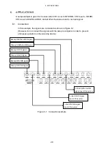


5. REMOTE CONTROL
26
5. REMOTE
CONTROL
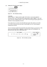
Connector used : Dsub 9 pin female (Inch screws for fixing the shell)
Figure 5-1 REMOTE connector
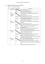
Table 5-1 Remote connector functions
Pin
No.
Name I/O
Description
1
AUTO SWITCHING
I
When the front-panel AUTO SWITCHING is set to SWITCH FAULT,
applying a low signal sets AUTO SWITCHING to DISABLED, and
applying a high signal (or opening the circuit) sets AUTO SWITCHING to
SWITCH FAULT.
When the front-panel AUTO SWITCHING is set to DISABLED, remote
control is not possible. Set AUTO SWITCHING to SWITCH FAULT using
keys to enable remote control.
2
SYNC SOURCE
I
Each time a low signal is applied, SYNC SOURCE switches between
PRIMARY and BACKUP.
3 SYNC
SOURCE
(PRIMARY)
O
Transmits a high signal when SYNC SOURCE is set to PRIMARY.
4 SYNC
SOURCE
(BACKUP)
O
Transmits a high signal when SYNC SOURCE is set to BACKUP.
5
FAULT INDICATOR
O
Transmits a high signal when an error occurs in PRIMARY or BACKUP.
Even when the error clears, the LT 4440/LT 444 retains the high signal
until the error is reset.
6
RESET
I
Apply a low signal to reset errors.
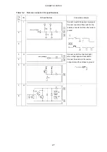
7 FAULT
IN
8 FAULT
INDICATOR-
O
Open during normal operation. Conducts current when the power is not
on or when there is an error in the input signal.
Use these pair of pins when you want to electrically isolate the
connected device from the LT 4440/LT 444.
(There is a photocoupler inside the LT 4440/LT 444 that is used for
isolation.)
9 GND
- Ground


