


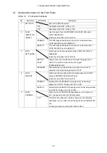


3. PANEL AND DIPSWITCH DESCRIPTION
11
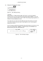
3.1 Front Panel
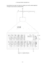
Figure 3-1 shows the front panel of the LT 4440/LT 444.
1 KEY
LOCK
Switch used to turn ON/OFF the key lock.
This key is also disabled while the instrument is starting up at power up.
2 FAULT
INDICATOR
This LED blinks when a level error is detected.
This LED keeps blinking even if the error is cleared.
The LED is cleared by clearing the error and pressing the RESET key.
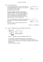
3 AUTO
SWITCHING
Switch used to set the operation mode to SWITCH FAULT or DISABLED when an
error is detected.
4 SYNC
SOURCE
Switch used to manually switch the signal passed to OUTPUT between PRIMARY
and BACKUP input.
5 FAULT
CHANNEL
The LED of the channel on which a level error was detected keeps illuminating.
This LED keeps illuminating even if the error is cleared.
The LED is cleared by clearing the error and pressing the RESET key.
3.2 Rear Panel
Figure 3-2 shows the rear panel of the LT 4440/LT 444.
6 REMOTE
Connector for remote control. It also has a level error status output.
7 PRIMARY/BACKUP/OUTPUT
OUTPUT connector that passes the signal from the PRIMARY or BACKUP signal
connector.
8 AC
inlet
Connect the power cord that came with the instrument. The operating supply voltage
range is 90 VAC to 250 VAC.
A fuse socket is under the AC inlet.


