


4. OPERATING PROCEDURE
17
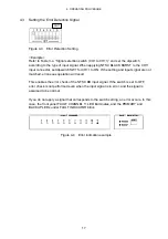
4.3 Setting the Error Detection Signal
Figure 4-3 Error Detection Setting
<Example>
Refer to Table 3-4, “Signal selection switch (CH1 to CH11)” and set the dipswitch
according to the type of input signal. When applying NTSC BLACK BURST to the CH11
input connector, set dipswitch SW1 for CH11 to ON. If the setting and input signal are not
matched, erroneous operation will result.
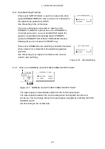
This enables the error check of the NTSC BB input signal. If the switch is set to OFF,
error check is not performed even when the input signal is in error, and the signal is
assumed to be normal.
If you do not apply a signal that corresponds to the switch setting, an error occurs. In this
case, the front panel FAULT CHANNEL 11 LED illuminates, and the PRIMARY and
BACKUP LEDs under FAULT INDICATOR blink.
Figure 4-4 Error indication example
CH11


