


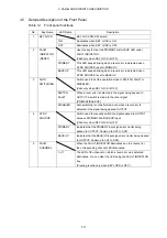


3. PANEL AND DIPSWITCH DESCRIPTION
12
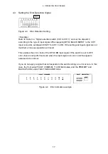
3.3 Side Panel
Figure 3-3 shows the side panel of the LT 4440/LT 444.
9 Serial
Number
Provide this number when contacting LEADER.
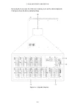
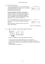
3.4 Dipswitch Section
Figure 3-4 shows the dipswitch section of the LT 4440/LT 444.
10 Dipswitch
cover
Removing the four screws from this cover enables you to set the internal dipswitch.
11 Signal selection switches CH1 to CH11
Dipswitches used to select the signal type for CH1 to CH11.
12 Error detection level selection switch
Switch used to set the error detection sensitivity to high level or low level for each
signal type selected.
13 Mode selection switch
Switch used to set the operation mode.
14 User defined volume
Adjust the USER ADJUST1 and USER ADJUST2 dials to adjust the error detection
levels.


