


4. OPERATING PROCEDURE
16
4. OPERATING
PROCEDURE
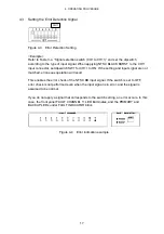
4.1 Signal Inputs and Outputs
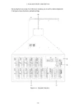
Figure 4-1 Signal Inputs and Outputs
At the BNC terminal on the rear panel, apply the primary signal to the PRIMARY
connector and the backup signal to the BACKUP connector. The OUTPUT connector
outputs either the PRIMARY or the BACKUP signal.
Both input and output connectors are designed for 75
Ω
systems. The signals applied to
PRIMARY and BACKUP must be of 75
Ω
impedance. In addition, the output from
OUTPUT must be terminated at 75
Ω
. Signals that are not selected by PRIMARY and
BACKUP of SYNC SOURCE are terminated internally at 75
Ω
.
*
When applying HD-SDI signals, use CH1 to CH6.
*
When operating in attenuator mode, use CH7 to CH11.
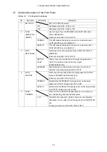
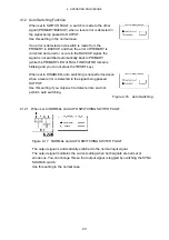
4.2 Turning the Dipswitches ON/OFF
Figure 4-2 ON/OFF of a dipswitch
When the slide switch of the dipswitch is in the ON position in Figure 4-2, the switch is
ON; when the slide switch is in the OFF position, the switch is OFF.
Input the primary signal
Input the backup signal
To the system signal input
OFF
ON


