


3. PANEL AND DIPSWITCH DESCRIPTION
14
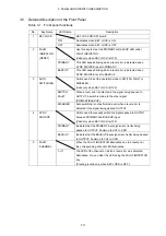
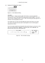
3.6 Detailed Description of the Dipswitch Section
Table 3-2 Signal selection switch (CH1 to CH11)
No.
SW No.
Selection Signal
All OFF
Disable (no error detection)
SW1 : ON
NTSC Black Burst
SW2 : ON
PAL Black Burst
SW3 : ON
SD-SDI (143 Mb/s)
SW4 : ON
SD-SDI (270 Mb/s) Tri-Level sync
SW5 : ON
AES/EBU digital audio
SW6 : ON
User Define 1 (adjust using USER ADJUST1)
SW7 : ON
User Define 2 (adjust using USER ADJUST2)
11
SW8 : ON
CH 1 to 6 : HD-SDI
CH 7 to 11 : Attenuation
*
Multiple selections on one dipswitch are prohibited except for Attenuation (SW8 on CH7 to CH11).
Table 3-3 Error detection low level selection switch (VREF LOW)
No.
SW No.
Error Detection Level Selection
All OFF
Disable (no error detection)
SW1 : ON
Select low level for NTSC Black Burst
SW2 : ON
Select low level for PAL Black Burst
SW3 : ON
Select low level for SD-SDI (143 Mb/s)
SW4 : ON
Select low level for SD-SDI (270 Mb/s)
Select low level for tri-level sync
SW5 : ON
Select low level for AES/EBU digital audio
SW6 : ON
Select user-defined level 1 (common to high level and low level)
SW7 : ON
Select user-defined level 2 (common to high level and low level)
12
SW8 : ON
Channels 1-6: Select low level for HD-SDI
*
Selecting both the error detection low level selection switch and error detection high level selection
switch on each signal is prohibited. For details, see section 4.4, “Setting the Error Detection Level.”


