
PAGE 19
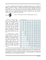
The ratio of transmitted to reflected energy is called the “standing wave ratio”, or SWR. An
SWR of 1 (sometimes written 1:1) indicates a perfect match. As more energy is reflected, the
SWR increases to 2, 3, or higher. As a general rule, modern solid state transmitters must operate
with an SWR of 2 or less. Tube exciters are somewhat more tolerant of high SWR. If a 50 ohm
antenna is resonant at the operating frequency, it will show an SWR close to 1. However, this is
usually not the case; operators often need to transmit at frequencies other than resonance,
resulting in a reactive antenna and a higher SWR.
where F = Forward power (watts), R = Reflected power (watts)
SWR is measured using a
device called an “SWR bridge”,
inserted in the transmission line
between the transmitter and the
antenna. This circuit measures
forward and reflected power from
which SWR may be calculated
(some meters calculate SWR for
you). More advanced units can
measure forward and reflected
power simultaneously, and show
these values and SWR at the same
time.
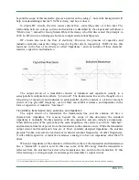
An antenna tuner is a device
used to cancel out the effects of
antenna reactance. Tuners add
capacitance to cancel out inductive
reactance in the antenna, and vice
versa. Simple tuners use variable
capacitors
and
inductors;
the
operator adjusts them by hand
while observing reflected power on
the SWR meter until a minimum
SWR
is
reached.
The
LDG
Electronics YT-450 automates this
process.
No tuner will fix a bad antenna. If the antenna is far from resonance, the inefficiencies
inherent in such operation are inescapable; it’s simple physics. Much of the transmitted power
may be dissipated in the tuner as heat, never reaching the antenna at all. A tuner simply “fools”
the transmitter into behaving as though the antenna were resonant, avoiding any damage that
might otherwise be caused by high reflected power. For best performance, the antenna used
should always be as close to resonance as is practical.
SWR
=
1
+
R
F
1
−
R
F