18
Appendix 1
DESIGNATION OF PINS OF RANGEFINDER EXTERNAL PLUGS
1. The plug to connect the external power supply and the remote trigger
button
- an external supply voltage of 12
±
2 V is applied to the pins 1,4 of the plug;
- the remote closure trigger button is connected to the pins 2,3 of the plug;
- a consumed current (average) is no more than 0.6 A.
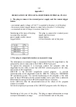
Numbering of the pins of the plug
to connect the external
power supply and the remote
trigger button
The plug to connect the external power
supply and the remote
trigger button
(viewed from the side of the pins)
Circuit
Pin
+ 12 V
1
TRIGGER
2
TRIGGER
3
0
4
2. The plug to output information on measured range
The information on measured range is transmitted from the rangefinder to the
computer by direct connection to the COM1 (3F8h) 9-pin port.
To operate the computer, it is necessary connect the computer with the
rangefinder by the cable, to start the LRF.EXE control program on the disk,
and switch on the rangefinder.
LRF.EXE is the EG-LRF rangefinder control program to provide
communication of the rangefinder with the IBM PC having the WINDOWS
XP operational system. For normal functioning of the program a free disk
space of about 700 Kbytes for the control module and a space that is unknown
beforehand for storage of the LRF.LOG output files are necessary.
In the LRF.LOG files the measurement data of the whole of the program
session is recorded.
See the description of operation of the LRF.EXE program in the file Help.txt.
Numbering of the pins of the plug
to output information on range
The plug to output information on range
(viewed from the side of the pins)
Содержание EG-LRF 20000
Страница 1: ...EG LRF 20000 technical description and instruction manual ...
Страница 3: ...3 Fig 1 EG LRF 20000 rangefinder set 1 Carrying case 2 Rangefinder 3 Accumulator battery 1 3 2 ...
Страница 7: ...7 ...
Страница 8: ...8 ...


