10
and continues operating until the stop pulse from the photoreceiver stops the
count of pulses from the timing oscillator of the time interval meter. The time
interval between the start and stop pulses is transformed into the information
corresponding to
a range to a target in metres that is displayed.
Besides the measured range, additional information is shown on the digital
display by the LEDs (Fig.5).
3.2.2. Rangefinder control in the CONTROL mode (the switch in the
position C)
After setting the supply switch to the position ON the value of minimum range
is output to the digital display. The value of minimum range depends on the
MIN RANGE position of the potentiometer handle and can be changed from
40 m for the extreme counter-clockwise position of the handle to 4500 m for
the extreme clockwise position of the handle. The accuracy of minimum range
setting is
±
20 m.
When pressing the START button in the CONTROL mode, the control range
is measured to check the serviceability of the rangefinder timer. In this case
there is no laser pulse. The START and STOP electrical pulses are formed not
by the photoreceiver, but by the central processor of the rangefinder. If a value
of minimum range is less than 280 m, the digital display outputs a control
range of 304
±
5 m. If a value of minimum range is more than 320 m, but less
than 3500 m, the control range is to be 3750
±
10 m. For minimum ranges
more than 4000 m the control range is 18,432
±
10 m.
A deviation of displayed values of control ranges more than
±
10 m from the
said nominal values is indicative of failure of the rangefinder.
Содержание EG-LRF 20000
Страница 1: ...EG LRF 20000 technical description and instruction manual ...
Страница 3: ...3 Fig 1 EG LRF 20000 rangefinder set 1 Carrying case 2 Rangefinder 3 Accumulator battery 1 3 2 ...
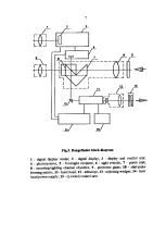
Страница 7: ...7 ...
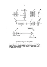
Страница 8: ...8 ...

