13
Since the laser head power supply produces high voltage that is a threat to
human life,
it is categorically prohibited to disassemble the housing of the
rangefinder
when there is an accumulator battery.
5.2. Measurement procedure
1) make sure that the
MIN RANGE
handle is set to the extreme left position
or to a required minimum range value (see 5.3);
2) set the
MODE
switch to the
F
position (range measurement to the first
target);
3) set the supply switch to the
ON
position. The rangefinder power supply is
on;
4) rotate the eyepieces to obtain a sharp image of the eyepiece reticule and of
the digital display;
5) look into the right eyepiece and set the cross-hairs exactly on a target. When
the green ready indicator in the digital display ocular lights, smoothly press
the trigger button. Do not release the trigger button and take the readings from
the display. The range in meters is displayed when holding the trigger button
pressed;
ATTENTION! If the trigger button is pressed before the green ready
indicator lights, measurement will be made with a delay until the green
indicator lights.
6) if the
M
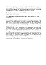
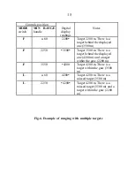
-indicator (multiple target) lights, carefully examine the target area
through the sight eyepiece to identify other targets (see Fig.6). For positive
identification of all targets the arrangement for minimum range setting can be
additionally used as explained in 5.3;
7) if the
C
-indicator lights, this means that one or more targets (without
indication of their number) are gated out by the minimum range setting.
Examine the target area through the sight eyepiece to identify the targets. If it
is necessary to measure a range to a target that is less than the minimum
range, reduce the minimum range setting and repeat the ranging procedure.
5.3. Use of arrangement for minimum range setting
To obtain reliable results, it is of first importance that an operator completely
understands the designation of the arrangement for minimum range setting.
Laser emission is reflected from various targets, and the receiver in the
rangefinder is not able to distinguish them from each other, so the shortest
range will be displayed, whether it be an obstacle or a target.
Содержание EG-LRF 20000
Страница 1: ...EG LRF 20000 technical description and instruction manual ...
Страница 3: ...3 Fig 1 EG LRF 20000 rangefinder set 1 Carrying case 2 Rangefinder 3 Accumulator battery 1 3 2 ...
Страница 7: ...7 ...
Страница 8: ...8 ...

