9
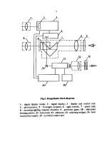
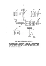
In the transmitting channel a laser pulse reflected from the target goes through
the protective glass (5), the receiving/sighting channel objective (4), the prism
unit (3) and is focused by the objective in the plane of the photosensitive area
of the photoreceiver (2).
The prism unit by its beam-splitting coating applied to the facet of one of the
prisms divides a laser pulse going through the objective into two portions. A
laser pulse at 1.054
µ
m passes to the photoreceiver, and a visible laser pulse is
reflected and focused in the plane of the eyepiece (1) reticule.
The boresight includes the objective (4) and the erecting prism unit (3)
integrated with the receiving channel, and the sight eyepiece (1).
The digital display unit consists of two mirrors (12) transmitting the image of
the digital display (11) to the eyepiece, and the display ocular (10).
The rangefinder operates in two modes: ranging mode (the
MODE
switch is in
the
F
or
L
position) and control mode (the
MODE
switch is in the
C
position)
When operating in the
F
mode, range measurement to the first target within
the rangefinder transmitter beam is carried out.
When operating in the
L
mode, range measurement to the last target within the
rangefinder transmitter beam is carried out.
When operating in the
C
mode, the value of minimum range is shown on the
digital display. By the
MIN RANGE
handle a necessary value of minimum
range is set within 40...4500 m.
3.2.1. Rangefinder operation in ranging mode (mode switch in F or L
position)
When the
ON
switch is switched on, the storage capacitor is getting charged
during
∼
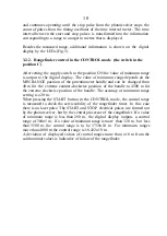
10 s. When it is charged, the ready indicator lights (Fig.4), and then
the storage capacitor is continuously recharged. To measure a range to a target,
the rangefinder cross-hairs at the center of the field of view of the sight
eyepiece is set on the target. When the trigger button is pressed, the storage
capacitor is discharged through the flash lamp of the laser, and a laser pulse is
generated. The major portion of a laser pulse is sent from the output of the
transmitting channel of the rangefinder to a target. At the same time a small
portion of the laser pulse hits the photosensitive area of the photoreceiver and
is transformed into an electric start pulse. The light pulse reflected from the
target is focused on the photosensitive area of the photoreceiver and is
transformed into an electric stop pulse. The time interval meter in the display
and control unit is started by the electric start pulse from the photoreceiver
Содержание EG-LRF 20000
Страница 1: ...EG LRF 20000 technical description and instruction manual ...
Страница 3: ...3 Fig 1 EG LRF 20000 rangefinder set 1 Carrying case 2 Rangefinder 3 Accumulator battery 1 3 2 ...
Страница 7: ...7 ...
Страница 8: ...8 ...

