background image

SDS1100 User Guide 

1: Introduction 

Connections and Pinouts 

Serial Port 

The unit has a female DCE DB25 serial port that supports RS-232 and RS-485/422 
serial standards (software selectable) up to 115 Kbps. 

Figure 1-1.  Serial Interface 


DB25 Serial Port 

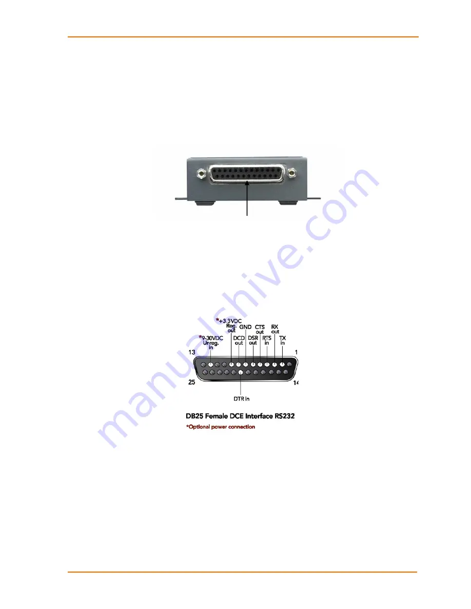
Serial Connector Pinouts 

The unit’s female DB25 connector provides an RS-232C, RS-485, or RS-422 DCE 
serial port. The default serial port settings are 9600 baud, 8 bits, no parity, and 1 stop 
bit. 

Figure 1-2.  DB25F DCE Serial Connector  


11 

Содержание SecureBox SDS1100

Страница 1: ...Part Number 900 354 Revision A April 2004 SecureBox SDS1100 User Guide ...

Страница 2: ...indows 95 Windows 98 Windows 2000 and Windows NT are trademarks of Microsoft Corp Netscape is a trademark of Netscape Communications Corporation Contacts Lantronix 15353 Barranca Parkway Irvine CA 92618 USA Phone 949 453 3990 Fax 949 453 3995 Technical Support Phone 800 422 7044 or 949 453 7198 Fax 949 450 7226 Online www lantronix com support E mail support lantronix com Sales Offices For a curre...

Страница 3: ... authority to operate this device The information in this guide may change without notice The manufacturer assumes no responsibility for any errors that may appear in this guide Note Export Control Classification Number 5A002 License exception ENC The following export agreement is required for encryption I agree that I will not export or re export this product or firmware to a national resident of...

Страница 4: ...96 Conducted Immunity Test IEC61000 4 8 1993 Magnetic Field Test IEC61000 4 11 1994 Voltage Dips Interrupts Test L V D Directive 73 23 EEC Supplementary Information This Class A digital apparatus complies with Canadian ICES 003 CSA and has been verified as being compliant within the Class A limits of the FCC Radio Frequency Device Rules FCC Title 47 Part 15 Subpart B CLASS A measured to CISPR 22 1...

Страница 5: ...SDS1100 User Guide 5 ...

Страница 6: ...l ship the replacement media to the customer In no event will Lantronix be responsible to the user in contract in tort including negligence strict liability or otherwise for any special indirect incidental or consequential damage or loss of equipment plant or power system cost of capital loss of profits or revenues cost of replacement power additional expenses in the use of existing software hardw...

Страница 7: ...16 Ethernet MAC Address__________________________________________ 16 Internet Protocol IP Address______________________________________ 16 Port Number ___________________________________________________ 16 Physically Connecting the Unit ________________________________________ 17 Methods of Assigning the IP Address ___________________________________ 18 DHCP _______________________________________...

Страница 8: ...Pack Control ___________________________________________________ 41 DisConnTime Inactivity Timeout ___________________________________ 42 Send Characters ________________________________________________ 43 Telnet Terminal Type_____________________________________________ 43 Channel Port Password _________________________________________ 43 Expert Settings___________________________________________...

Страница 9: ...______________________________54 Technical Support __________________________________________________ 54 Monitor Mode______________________________________________________ 58 Via the Serial Port _______________________________________________ 58 Via the Network_________________________________________________ 58 Monitor Mode Commands_________________________________________ 58 6 Binary to Hexadeci...

Страница 10: ...uipment Data Display Devices Protocol Support The SDS1100 uses the Internet Protocol IP for network communications and the Transmission Control Protocol TCP to assure that no data is lost or duplicated and that everything sent to the connection arrives correctly at the target Other supported protocols are listed below ARP UDP TCP ICMP Telnet TFTP AutoIP DHCP HTTP and SNMP for network communication...

Страница 11: ... RS 485 422 serial standards software selectable up to 115 Kbps Figure 1 1 Serial Interface DB25 Serial Port Serial Connector Pinouts The unit s female DB25 connector provides an RS 232C RS 485 or RS 422 DCE serial port The default serial port settings are 9600 baud 8 bits no parity and 1 stop bit Figure 1 2 DB25F DCE Serial Connector 11 ...

Страница 12: ...Port The unit s back panel contains a 9 30VDC power plug and an RJ45 10 100 Ethernet port Figure 1 3 Network Interface Ethernet Connector Pinouts The unit supports 10 Mbps Ethernet through an RJ45 connector Figure 1 4 RJ45 Ethernet Connector 12 ...

Страница 13: ...link activity steady green Valid 100 Mbps network connection 100Mbps link activity blinking Network packets transmitting and receiving Collision blinking red Network collisions Diagnostic steady red and status blinking green 2 blinks RAM error 4 blinks EEPROM checksum error 5 blinks Duplicate IP address on network Diagnostic blinking red and status blinking green 5 blinks No DHCP response Status s...

Страница 14: ...S 422 485 Network Interface 10 100 RJ45 Ethernet Power Supply External adapter included 120VAC USA 100 240 VAC Universal with regional connectors Power Input 9 30 VDC or 9 24 VAC 1W maximum Dimensions Height 2 3 cm 0 9 in Width 6 4 cm 2 5 in Depth 9 0 cm 3 5 in Weight 0 35 Kg 0 8 lbs Temperature Operating range 5 to 50 C 41 to 122 F Storage range 40 to 66 C 40 to 151 F Relative Humidity Operating ...

Страница 15: ...SDS1100 User Guide 1 Introduction 15 ...

Страница 16: ...14 01 18 or 00 20 4A 14 01 18 Internet Protocol IP Address Every device connected to an IP network must have a unique IP address This address is used to reference the specific unit Port Number Every TCP connection and every UDP datagram is defined by a destination IP address and a port number For example a Telnet application commonly uses port number 23 A port number is similar to an extension on ...

Страница 17: ...r to the numbers in the previous figure 1 Connect a serial device to your unit See Connections and Pinouts in the Introduction for more information about what kinds of device attachments the unit supports 2 Connect an Ethernet cable to the 10 100 port 3 Supply power to your unit using the power supply that was included in the packaging Note The required input voltage is 9 30 VDC or 9 24 VAC 1 W ma...

Страница 18: ...one person at a time can be logged into the configuration port port 9999 This eliminates the possibility of several people simultaneously attempting to configure the unit AutoIP This automatic method is appropriate when you have a small group of hosts rather than a large network This method allows the hosts to negotiate with each other and assign addresses in effect creating a small network Serial...

Страница 19: ...0 which automatically enables Auto IP within the unit AutoIP is an alternative to DHCP that allows hosts to automatically obtain an IP address in smaller networks that may not have a DHCP server A range of IP addresses from 169 254 0 1 to 169 254 255 1 has been explicitly reserved for AutoIP enabled devices The range of Auto IP addresses is not to be used over the Internet If your unit cannot find...

Страница 20: ...t button on the Task Bar and select Run 4 Enter your CD drive letter colon backslash deviceinstaller exe e g E deviceinstaller exe 5 Click the DeviceInstaller button The installation wizard window displays 6 Respond to the installation wizard prompts When prompted to select an installation type select Typical Assign IP Address and Network Class 1 Click the Start button on the Task Bar and select P...

Страница 21: ... icon The Assign IP Address window displays Figure 2 4 Assign IP Address Window Device Identification 3 Enter the Hardware or Ethernet address of the device The following Assign IP Address window appears Figure 2 5 Assign IP Address Window Assignment Method 21 ...

Страница 22: ...tomatically to enable BOOTP DHCP or Auto IP on the device 5 Click Next The following Assign IP Address window appears Figure 2 6 Assign IP Address Window IP Settings 6 Enter the IP address subnet mask and gateway being assigned to the device Enter this information in XXX XXX XXX XXX format 7 Click Next The following Assign IP Address window appears 22 ...

Страница 23: ...ix devices on the network so that you can manage and configure it To perform this step click the Search icon The device should be located by DeviceInstaller and added into the Device List Now you can manage configure the unit so that it works with the serial device on the network Opening a Configuration Window Once the device is added into the list use the Configure Upgrade Telnet or Web icons to ...

Страница 24: ...le in case for example someone changes the configuration of the unit incorrectly The Configure icon sends a saved file to the unit ARP and Telnet The unit s IP address must be configured before a network connection is available If the unit has no IP address you can use the Address Resolution Protocol ARP method from UNIX and Windows based systems to assign a temporary IP address If you want to ini...

Страница 25: ... If you wait longer than three seconds the unit will reboot Figure 2 12 Telnet to Port 9999 telnet 191 12 3 77 9999 5 Set all required parameters Note The IP address you just set is temporary and will revert to the default value when the unit s power is reset unless you log into the unit and store the changes permanently Refer to the chapter on configuration for instructions on permanently configu...

Страница 26: ...3 Select 0 Server Configuration and follow the prompts until you get to IP address 4 Enter the new IP address Subnet Mask and Gateway if applicable 5 Select 9 to save the configuration and exit Setup Mode The unit performs a power reset 26 ...

Страница 27: ...d method Use a Telnet connection to configure the unit over the network Use a terminal or terminal emulation program to access the serial port locally The unit s configuration is stored in nonvolatile memory NVRam and is retained without power You can change the configuration at any time The unit performs a reset after the configuration has been changed and stored Configuring via Web Browser If yo...

Страница 28: ...figure the SDS1100 as shown in Figure 3 3 Serial cabling lets you view pinouts for the SDS serial port View SDS Configuration Tutorials provide step by step instructions for configuring encryption serial tunneling and the Com Port Redirector Technical Support lets you download the latest firmware for your SDS and view documentation 28 ...

Страница 29: ...nfiguration parameters later in this chapter Note The sequence of parameters explained and examples shown later in this chapter correspond to the Setup Mode window rather than to the WEB Manager sub pages 2 When you are finished click the Update Settings button to save your settings For example to enter server properties 1 Click the Server Properties button The Server Properties section of the Web...

Страница 30: ...Setup Mode window via a serial connection 4 Click the Update Settings button Configuring via the Setup Mode Window Using a Telnet Connection To configure the unit over the network establish a Telnet connection to port 9999 Note You can also use the Telnet to Device icon on the DeviceInstaller Device Management window to establish the connection 1 From the Windows Start menu click Run and type the ...

Страница 31: ...onds Figure 3 6 Setup Mode Window 3 Select an option on the menu by entering the number of the option in the Your choice field and pressing Enter 4 To enter a value for a parameter type the value and press Enter or to confirm a current value just press Enter 5 When you are finished save the new configurations option 9 The unit will reboot 31 ...

Страница 32: ...nfiguration a terminal or a PC running a terminal emulation program can be connected to the unit s serial port channel 1 The terminal or emulation should be configured for 9600 baud 8 bit no parity 1 stop bit and no flow control 1 Cycle the unit s power power off and back on After power up the self test begins and the diagnostic and status LEDs start blinking 2 Type three lowercase x characters xx...

Страница 33: ...Address The gateway address or router allows communication to other LAN segments The gateway address should be the IP address of the router connected to the same LAN segment as the unit The gateway address must be within the local network Netmask A netmask defines the number of bits taken from the IP address that are assigned for the host section Note Class A 24 bits Class B 16 bits Class C 8 bits...

Страница 34: ...required to access the Setup Mode window via a serial connection DHCP Naming A DHCP name is a unique identifier used for managing multiple DHCP hosts on a network Your unit ships with a default DHCP name of Cxxxxxx where xxxxxx are the last six digits of the Mac address You can change the DHCP name up to eight characters when configuring the server on the Setup Mode window Change the DHCP name to ...

Страница 35: ...are 300 600 1200 2400 4800 9600 default 19200 38400 57600 and 115200 bits per second I F Interface Mode The Interface I F Mode is a bit coded byte that you enter in hexadecimal notation Note If you do not want to convert the binary numbers to hexadecimals yourself look up the values in Table 6 6 Interface Mode Options in the Binary to Hexadecimal chapter Table 3 3 Interface Mode Options I F Mode O...

Страница 36: ... 1 65535 except for the following reserved port numbers Table 4 5 Reserved Port Numbers Port Numbers Reserved for 1 1024 Reserved well known ports 9999 Telnet setup 14000 14009 Reserved for Redirector 30718 Reserved 77FEh Warning We recommend that you not use the reserved port numbers for this setting as incorrect operation may result The port number functions as the TCP UDP source port number for...

Страница 37: ...onn D disconn N unreachable 1 Startup No active startup 0 0 0 0 With any character 0 0 0 1 With active DTR 0 0 1 0 With a specific start character 0 0 1 1 Manual connection 0 1 0 0 Autostart 0 1 0 1 Hostlist 0 0 1 0 Datagram Type Directed UDP 1 1 0 0 Modem Mode Full Verbose 1 0 1 1 0 Without Echo 0 0 1 1 0 Numeric modem result codes 1 0 1 1 1 Manual Connection When you use manual connection you ar...

Страница 38: ...connects to the remote IP address and remote port specified Datagram Type When selecting this option you will be prompted for the Datagram type Enter 01 for directed or broadcast UDP Hostlist If you enable this option the Lantronix unit scrolls through the hostlist until it connects to a device listed in the hostlist table Once it connects the unit stops trying to connect to any others If this con...

Страница 39: ...phone charges for each connection Modem Mode allows you to replace modems with SDS1100s and to use an Ethernet connection instead of a phone call without having to change communications applications and make potentially expensive phone calls To select Modem Mode set the Connect Mode to C6 no echo D6 echo with full verbose or D7 echo with 1 character response Note If the unit is in Modem Mode and t...

Страница 40: ... network to the serial port n 1 9 enables the ability to make a connection from the network to the serial port n 1 9 is invalid ATEn Enables or disables character echo and responses n 0 disables character echo and responses n 1 enables character echo and responses ATVn Enables 1 character response or full verbose n 0 enables 1 character response n 1 enables full verbose Note These AT commands are ...

Страница 41: ...o function properly Ctrl D will only be detected going from the serial port to the network Flush Mode Buffer Flushing Using this parameter you can control line handling and network buffers with connection startup and disconnect You can also select between two different packing algorithms Note If you do not want to convert the binary numbers to hexadecimals yourself look up the values in Table 6 5 ...

Страница 42: ...rs equal to the force transmit set then the SDS will package up the serial data currently in the buffer and send it to the network Trailing Characters In some applications CRC Checksum or other trailing characters follow the end of sequence character this option helps to adapt frame transmission to the frame boundary Send Characters If 2 Byte Send Character Sequence is enabled the unit interprets ...

Страница 43: ...ode above If this option is enabled you can use the terminal name for the Telnet terminal type Enter only one name If the terminal type option is enabled the unit also reacts to the EOR end of record and binary options which can be used for applications like terminal emulation to IBM hosts Channel Port Password This parameter appears only if the channel port password option is enabled in Disconnec...

Страница 44: ...ne else could capture these settings Figure 3 13 Security Settings Disable SNMP This setting allows you to disable the SNMP protocol on the unit preventing SNMP management software from communicating with the SDS SNMP Community Name This option allows you to change the SNMP Community Name on the unit This allows for ease of management and possibly some security If someone tries to violate security...

Страница 45: ...d that protects the Configuration Menu via Telnet and Web pages The Y Yes option allows you to set an extended security password of 16 characters for protecting Telnet access Enable Encryption Rijndael is the block cipher algorithm chosen by the National Institute of Science and Technology NIST as the Advanced Encryption Standard AES to be used by the US government The SDS supports 128 192 and 256...

Страница 46: ...ption only applies to the port selected for tunneling data default 10001 regardless of whether you are using TCP or UDP Generally one of two situations applies Encrypted SDS to SDS communication Be sure to configure both SDS devices with the same encryption key Third party application to SDS encrypted communication SDS uses standard AES encryption protocols To communicate successfully products and...

Страница 47: ... 0x0D CR All other parameters 0 Expert Settings Defaults TCP keepalive 45 seconds ARP cache timeout 600 seconds Security Settings Defaults SNMP Enabled SNMP community name public Telnet setup Enabled TFTP download Enabled Port 77FEh Enabled Web Server Enabled ECHO Disabled Encryption Disabled Enhanced password Disabled Exit Configuration Mode Select 8 to exit the configuration mode without saving ...

Страница 48: ...face CBXW COB via TFTP or DeviceInstaller Via DeviceInstaller After downloading the firmware to your computer you can use DeviceInstaller to install it If you haven t already installed DeviceInstaller from the product CD see Install the DeviceInstaller 1 Download the updated firmware files from www lantronix com or ftp ftp lantronix com and store them in a subfolder on your computer 2 Click the St...

Страница 49: ...taller highlight the device in the device list and click the Upgrade button 5 Select a custom installation by specifying the individual files and clicking Next Figure 4 3 Device Upgrade Wizard Step 1 6 Click the Browse button to select the location of the firmware file being loaded then click Next 49 ...

Страница 50: ...the firmware files are located To download new firmware using a TFTP client 1 Use a TFTP client to send a binary file SD11 ROM to the unit to upgrade the unit s internal operational code and cbx cob to upgrade its internal Web interface Note TFTP requires the ROM binary version of the unit s internal operational code 2 Make sure the Put and Binary options at the top of the window are selected 3 En...

Страница 51: ...e Troubleshooting chapter 2 Send the firmware to the receiving unit using the SF command where x x x x is the receiving unit s IP address Figure 4 6 Sending Firmware to Another Unit SF x x x x The receiving unit performs a power reset after the firmware has been loaded and stored Note You can only update your unit s internal Web interface using TFTP or DeviceInstaller Via the Serial Port The follo...

Страница 52: ...wnload the firmware to the unit using the DL command 3 Select Send Text File and select the SD11 HEX file to be downloaded The downloaded file must be the HEX ASCII version 4 After the final record is received the unit checks the integrity of the firmware image before programming the new firmware in the flash ROM The following message displays when the firmware upgrade is complete Figure 4 7 Firmw...

Страница 53: ...SDS1100 User Guide 4 Updating Firmware 53 ...

Страница 54: ...your unit s IP address is unique Technical Support If you are experiencing an error that is not described in this chapter or if you are unable to fix the error you may Check our online knowledge base at www lantronix com support com E mail us at support lantronix com Call us at 800 422 7044 Domestic 949 453 7198 International 949 450 7226 Fax Our phone lines are open from 6 00AM 5 30 PM Pacific Ti...

Страница 55: ... the ARP method the Press Enter to go into Setup Mode error described below displayed Now when you Telnet to the SDS the connection fails When you Telnet into port 1 on the SDS you are only assigning a temporary IP address When you Telnet into port 9999 and do not press Enter quickly the SDS will reboot causing it to lose the IP address Telnet back into Port 1 Wait for it to fail then Telnet to po...

Страница 56: ...aged or the unit is not plugged into power properly Try plugging the SDS into another outlet If this does not fix the problem contact your dealer or Lantronix Technical Support for a replacement The SDS1100 will not power up properly and the LEDs are flashing Various Consult the LEDs section in the Introduction chapter or the Quick Start for the LED flashing sequence patterns Call Lantronix Techni...

Страница 57: ... using the correct serial cable and the SDS should be set up correctly but you are not communicating with your device attached to the SDS across the network If you are sure that the serial cable is correct then you may not be connecting to the correct socket of the SDS Another possibility is that the SDS is not set up correctly to make a good socket connection to the network You can check to see w...

Страница 58: ...onnections type xx2 or yyy A 0 prompt indicates that you have successfully entered Monitor Mode Via the Network To enter Monitor Mode using a Telnet connection 1 First establish a Telnet session The following message displays Figure 5 1 Entering Monitor Mode Via the Network 2 Type M upper case A 0 prompt indicates that you have successfully entered Monitor Mode Monitor Mode Commands The following ...

Страница 59: ...ARP Table Shows the unit s ARP table entries TT TCP Connection Table Shows all incoming and outgoing TCP connections NC Network Connection Shows the unit s IP configuration RS Reset Resets the unit s power QU Quit Exits diagnostics mode G0 G1 GE GF Get configuration from memory page Gets a memory page of configuration information from the device S0 S1 SE SF Set configuration to memory page Sets a ...

Страница 60: ...cimal notation The following tables are included Binary to Hexadecimal Conversions Connect Mode Options Disconnect Mode Options Flush Mode Buffer Flushing Options Interface Mode Options Pack Control Options Converting Binary to Hexadecimal Hexadecimal digits have values ranging from 0 to F which are represented as 0 9 A for 10 B for 11 etc To convert a binary value for example 0010 0011 to a hexad...

Страница 61: ...nection Active Connection Startup Hostlist Hex Never None quiet No active startup N A Never None quiet Any character 1 Never None quiet Active DTR 2 Never None quiet CR 0x0D 3 Never None quiet Manual connection 4 Never None quiet Autostart 5 Never None quiet UDP C Never Character No active startup 10 Never Character Any character 11 Never Character Active DTR 12 Never Character CR 0x0D 13 Never Ch...

Страница 62: ...None quiet Autostart C5 Unconditionally None quiet UDP CC Unconditionally Character No active startup D0 Unconditionally Character Any character D1 Unconditionally Character Active DTR D2 Unconditionally Character CR 0x0D D3 Unconditionally Character Manual connection D4 Unconditionally Character Autostart D5 Unconditionally Character UDP DC Never None quiet No active startup Hostlist N A Never No...

Страница 63: ...nconditionally None quiet No active startup Hostlist N A Unconditionally None quiet Any character Hostlist E1 Unconditionally None quiet Active DTR Hostlist E2 Unconditionally None quiet CR 0x0D Hostlist E3 Unconditionally None quiet Manual connection Hostlist N A Unconditionally None quiet Autostart Hostlist E5 Unconditionally None quiet UDP Hostlist N A Unconditionally Character No active startu...

Страница 64: ...SDS1100 User Guide 6 Binary to Hexadecimal With DTR Without echo 46 With DTR 1 character response 47 Unconditionally Echo D6 Unconditionally Without echo C6 Unconditionally 1 character response C7 64 ...

Страница 65: ...able Enable C0 Enable Enable Enable Enable D0 Enable Enable Enable Enable E0 Enable Enable Enable Enable Enable F0 Enable Enable 1 Enable Enable Enable 11 Enable Enable Enable 21 Enable Enable Enable Enable 31 Enable Enable Enable 41 Enable Enable Enable Enable 51 Enable Enable Enable Enable 61 Enable Enable Enable Enable Enable 71 Enable Enable Enable 81 Enable Enable Enable Enable 91 Enable Enab...

Страница 66: ...Disable D8 Enable Enable Disable Enable E8 Enable Enable Enable Disable Enable F8 Disable Enable 9 Enable Disable Enable 19 Disable Enable Enable 29 Enable Disable Enable Enable 39 Enable Disable Enable 49 Enable Enable Disable Enable 59 Enable Disable Enable Enable 69 Enable Enable Disable Enable Enable 79 Enable Disable Enable 89 Enable Enable Disable Enable Enable 99 Enable Disable Enable Enabl...

Страница 67: ...on Enable A0 Active connection Passive connection Enable B0 Disconnect Enable C0 Active connection Disconnect Enable D0 Passive connection Disconnect Enable E0 Active connection Passive connection Disconnect Enable F0 Active connection 1 Active connection Active connection 11 Passive connection Active connection 21 Active connection Passive connection Active connection 31 Disconnect Active connect...

Страница 68: ...Passive connection Disconnect Passive connection 62 Active connection Passive connection Disconnect Passive connection 72 Passive connection Enable 82 Active connection Passive connection Enable 92 Passive connection Passive connection Enable A2 Active connection Passive connection Passive connection Enable B2 Disconnect Passive connection Enable C2 Active connection Disconnect Passive connection ...

Страница 69: ...tive connection Disconnect Active connection Passive connection Enable D3 Passive connection Disconnect Active connection Passive connection Enable E3 Active connection Passive connection Disconnect Active connection Passive connection Enable F3 Disconnect 4 Active connection Disconnect 14 Passive connection Disconnect 24 Active connection Passive connection Disconnect 34 Disconnect Disconnect 44 ...

Страница 70: ...tive connection Disconnect 75 Active connection Disconnect Enable 85 Active connection Active connection Disconnect Enable 95 Passive connection Active connection Disconnect Enable A5 Active connection Passive connection Active connection Disconnect Enable B5 Disconnect Active connection Disconnect Enable C5 Active connection Disconnect Active connection Disconnect Enable D5 Passive connection Dis...

Страница 71: ...Disconnect Enable D6 Passive connection Disconnect Passive connection Disconnect Enable E6 Active connection Passive connection Disconnect Passive connection Disconnect Enable F6 Active connection Passive connection Disconnect 7 Active connection Active connection Passive connection Disconnect 17 Passive connection Active connection Passive connection Disconnect 27 Active connection Passive connec...

Страница 72: ...e connection Disconnect Enable A7 Active connection Passive connection Active connection Passive connection Disconnect Enable B7 Disconnect Active connection Passive connection Disconnect Enable C7 Active connection Disconnect Active connection Passive connection Disconnect Enable D7 Passive connection Disconnect Active connection Passive connection Disconnect Enable E7 Active connection Passive c...

Страница 73: ...22 485 7 No 2 C9 RS 422 485 7 Even 1 79 RS 422 485 7 Even 2 F9 RS 422 485 7 Odd 1 59 RS 422 485 7 Odd 2 D9 RS 422 485 8 No 1 4D RS 422 485 8 No 2 CD RS 422 485 8 Even 1 7D RS 422 485 8 Even 2 FD RS 422 485 8 Odd 1 5D RS 422 485 8 Odd 2 DD RS 422 485 2 Wire 7 No 1 4B RS 422 485 2 Wire 7 No 2 CB RS 422 485 2 Wire 7 Even 1 7B RS 422 485 2 Wire 7 Even 2 FB RS 422 485 2 Wire 7 Odd 1 5B RS 422 485 2 Wir...

Страница 74: ...No 12ms 10 2 Byte Sequence No 52ms 11 2 Byte Sequence No 250ms 12 2 Byte Sequence No 5sec 13 2 Byte Sequence 1 12ms 14 2 Byte Sequence 1 52ms 15 2 Byte Sequence 1 250ms 16 2 Byte Sequence 1 5sec 17 2 Byte Sequence 2 12ms 18 2 Byte Sequence 2 52ms 19 2 Byte Sequence 2 250ms 1A 2 Byte Sequence 2 5sec 1B 1 Byte Sequence No 12ms Yes 20 1 Byte Sequence No 52ms Yes 21 1 Byte Sequence No 250ms Yes 22 1 B...

Страница 75: ... after Sendcharacter He x 2 Byte Sequence No 250ms Yes 32 2 Byte Sequence No 5sec Yes 33 2 Byte Sequence 1 12ms Yes 34 2 Byte Sequence 1 52ms Yes 35 2 Byte Sequence 1 250ms Yes 36 2 Byte Sequence 1 5sec Yes 37 2 Byte Sequence 2 12ms Yes 38 2 Byte Sequence 2 52ms Yes 39 2 Byte Sequence 2 250ms Yes 3A 2 Byte Sequence 2 5sec Yes 3B 75 ...

Отзывы: