background image

61 


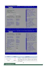
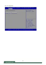
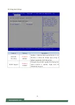
Trusted Computing (PTT Enable) 


Feature 

Options 

Description 

Security Device 

Support 

Enabled 

Disabled 

Enables or disables BIOS support for security device. 
By disabling this function, OS will not show Security 
Device. TCG EFI protocol and INT1A interface will not 
be available. 

Содержание NCA-5520

Страница 1: ...1 NCA 5520 User Manual Version 1 0 Date of Release 2020 02 13 Network Appliance Platform Hardware Platforms for Network Computing...

Страница 2: ...provements to the products described in this manual at any time without notice No part of this manual may be reproduced copied translated or transmitted in any form or by any means without the prior w...

Страница 3: ...the instruction manual may cause harmful interference to radio communications The operation of this equipment in a residential area is likely to cause harmful interference in which case users will be...

Страница 4: ...n a closed or multi unit rack assembly the operating ambient temperature of the rack environment may be greater than room ambient Therefore consideration should be given to installing the equipment in...

Страница 5: ...ante peut ne pas tre ad quate pour refroidir l quipement une temp rature de fonctionnement acceptable sans circulation adapt e V rifiez que votre site propose une circulation d air ad quate V rifiez q...

Страница 6: ...n result in an EXPLOSION Leaving a BATTERY in an extremely high temperature surrounding environment can result in an EXPLOSION or the leakage of flammable liquid or gas A BATTERY subjected to extremel...

Страница 7: ...ening the Chassis 24 Installing the CPU 25 Installing the Disk Drive s 31 Installing the NIC Modules 33 Replacing the Cooling Fans 35 Replacing the Power Supply Units 36 Installing the mSATA 37 Instal...

Страница 8: ...Redirections 119 Appendix E Programming Generation 3 LAN Bypass 120 Appendix F Installing Intel LAN Controller Driver for Linux 121 Appendix G Terms and Conditions 122 Warranty Policy 122 RMA Service...

Страница 9: ...tures NCA 5520A Intel C626 w BMC 4x 10G SFP MGMT NCA 5520B Intel C621 4x GbE RJ45 MGMT Optional Accessories Model Name Description NCS2 IGM806A 8 port NIC with Intel i350 AM4 and 4 Pairs G3 Bypass NCS...

Страница 10: ...1x ATX Power Switch Console 1x RJ45 1x mini USB Console USB 2x USB 3 0 LCD Module N A Optional Display 1x VGA Internal Pin Header Power input AC power inlet on PSU Storage HDD SSD Support 2x 2 5 Inter...

Страница 11: ...For software reset F2 LED Indicators F3 Console Port 1x RJ45 console port F4 USB Ports 2x USB 3 0 port F5 RJ45 Ports or SFP Ports 4x RJ45 port with LED 4x 10G SFP port F6 MGT LAN Port 1x RJ45 for MGT...

Страница 12: ...slot R2 Alarm off Button An audible alarm will sound when the system s redundant power is missing Press this button to turn the alarm off R3 Power Switch 1x Power button R4 Fans 4 x Independent Swapp...

Страница 13: ...OS mSATA LPC TPM SATAIII 5 PCIe x4 SATA0 PCIe x8 PCIe x8 or PCIEx4 2 auto selection SPI PCIe x8 PCIe x8 FPGA PCIe x8 FPGA PCIe x8 DMI 4 BIOS Dual BIOS U 2 connector reserved for 2U PCIe x1 PCIe x1 AST...

Страница 14: ...14 Motherboard Layout The motherboard layout shows the connectors and jumpers on the board Refer to the following picture as a reference of the pin assignments and the internal connectors...

Страница 15: ...B Power CONN Not connected Reserve 5 JFAN4 PWM FAN CONN 1 PWM Input 2 3 FAN Tachometer Output 4 P12V 5 GND 6 JFAN3 PWM FAN CONN 7 JFAN2 PWM FAN CONN 8 JFAN1 PWM FAN CONN 10 JDDR4 DDR4 Channel C DIMM0...

Страница 16: ...16...

Страница 17: ...FM_PHY_DIS B50 BMC_RGMII_RXCTL A50 B10 GND A10 PCIE_WAKE B51 BMC_RGMII_RXD0 A51 B11 GND A11 PLT_RST B52 BMC_RGMII_RXD1 A52 GND B12 USB30_TX3P A12 GND B53 BMC_RGMII_RXD2 A53 B13 USB30_TX3N A13 BMC_UAR...

Страница 18: ...EED B74 GND A74 B34 PCIE_PTX_C_LANRX _N1 A34 LED_GBE2_ACT B75 A75 B35 GND A35 LED_GBE2_LOW_SP EED B76 A76 B36 PCIE_PRX_C_LANTX _P1 A36 FM_T2_LVC3_MOD _ABS0 B77 GND A77 P3V3 B37 PCIE_PRX_C_LANTX _N1 A3...

Страница 19: ...19 48 47 22 21 GND 50 GND 49 24 P3V3_NGFF 23 SATA_PRX_DTX_P16 52 P3V3_NGFF 51 26 GND 25 SATA_PRX_DTX_N16 54 GND 53 GND 28 27 GND 56 55 26 JRISER1 CPU PCIe GEN3 Slot Support x8 or 2x4 28 JLCM1 either J...

Страница 20: ...upports up to 6Gb s 33 JSATA1 SATA CONN Supports up to 6Gb s 34 JSATA4 SATA CONN Supports up to 6Gb s 35 JSATA2 SATA CONN Supports up to 6Gb s 36 UPCH1 PCH Lewisburg Model PCH SKU NCB 3230A C627 NCB 3...

Страница 21: ...th IO 32302 NCB 3230C Copper x4 With IO 32301 39 JATX3 ATX Power CONN 5V 5VSB 12VSB Must be connected 1 GND 2 P5V 3 GND 4 P5V_SB 5 GND 6 P12V_STBY_PSU 7 GND 8 P12V_STBY_PSU 40 JPMB1 ATX Power On SMbus...

Страница 22: ...ROM to be flashed Jumper 1 2 3 4 Flash 1 st BIOS Jumper 1 3 2 4 Flash 2 nd BIOS 46 BAT1 PCH RTC Battery Hold 47 BZ1 Buzzer 48 JOPEN1 Case Open Function Pin Header High Case Open Low Normal 49 JPCIESL...

Страница 23: ...54 JPCIESL3 CPU PCIe GEN3 Slot Support x8 or 2x4 55 JPCIESL4 CPU PCIe GEN3 Slot Support x8 or 2x4 56 JGP1 GPIO Pin Header 1 GPO_B_1 2 GPI_B_1 3 GPO_B_2 4 GPI_B_2 5 GPO_B_3 6 GPI_B_3 7 GPO_B_4 8 GPI_B_...

Страница 24: ...system please remove all power connections to completely shut down the device Also please wear ESD protection gloves when conducting the steps in this chapter Opening the Chassis 1 Loosen the 2 screw...

Страница 25: ...requirements Installing the processor onto the motherboard involves two stages 1 Mount the processor onto the heat sink to make a PHM Processor Heat Sink Module 2 Install the PHM onto the motherboard...

Страница 26: ...corners an important indicator used to align this carrier with the processor and the bolster plate correctly Dust Cover This cover is used to protect the package land surface of the processor from con...

Страница 27: ...the carrier Note During assembly it is essential to have 1 PIN1 on the processor aligned with that on the carrier and 2 the alignment features on the top and the bottom of the CPU aligned with the co...

Страница 28: ...ing sound when the latch clicks into place 6 Go through the four corners to check if the latches are engaged If correctly latched the corners of the carrier should be tightly attached to the heat sink...

Страница 29: ...cket carefully hold the PHM while lowering it vertically to engage it to the alignment pins of the bolster plate 4 Make sure the PHM is sitting horizontally on the bolster plate 5 Use a torque driver...

Страница 30: ...30 Note When fastening 3 and 4 nuts the gap between the metal spring leaf of the bolster plate and the PHM will gradually diminish as you drive the nuts...

Страница 31: ...HDD SSD slot HDD preferred drive bay The following will discuss disk drive installation procedures based on their HDD SSD designs 1 Power off the system 2 Locate the 2 5 disk bay on the front panel 3...

Страница 32: ...e SATA contacts inside the system 5 Install the tray back to the original position with the screw Make sure the notch of the tray s side engages properly into the pin as shown in the picture 6 Connect...

Страница 33: ...odule slots for network bandwidth expansion Please follow the steps for installation 1 On the front panel select a NIC Ethernet module slot 2 Rotate clockwise and loosen the two lock screws 3 Remove t...

Страница 34: ...hown in the image below is for reference only 5 Once the module is firmly seated rotate counter clockwise and tighten the two lock screws Align the golden fingers to the socket on the motherboard care...

Страница 35: ...cooling fan simply reverse the steps to install the fan back onto the enclosure and the system 1 Locate the cooling fans at the rear panel 2 From the rear side of the fan loosen the screw that secures...

Страница 36: ...ted that the NCA 5520 series supports 550W 800W depending on the ordering preferences Please prepare the power supply units matching this capacity 1 On the rear panel locate the power supply units and...

Страница 37: ...installing an mSATA card 1 Locate the mSATA socket Align the notch of the module with the socket key in the slot 2 Insert the module at 30 degrees into the socket until it is fully seated in the conne...

Страница 38: ...ts both sides If you do not plan to fill up all the sockets with 10 memory modules always start with the blue ones for optimal performance 1 Power off the system 2 Pull open the DIMM slot latches 3 Al...

Страница 39: ...the Slide Rail Kit and Short Ear Brackets the system can be secured on the rack The Slide Rails can secure the system while providing making the equipment easy to access The Ear Brackets fix the syste...

Страница 40: ...ng rail on the system 2 x Slide Rails The rail consists of the following parts Attaching the Rail Brackets 2 Unpack a slide rail and slide the Inner Channel all the way to the end 3 Stretch the Rail B...

Страница 41: ...he four buttons on the side panel as shown in the picture 6 Carefully pull the Rail Bracket backward to have the buttons locked into the four screw holes as shown in the picture 7 Repeat Steps 5 6 to...

Страница 42: ...ide rail kit does NOT require screw fixing Simply aim at 3 available screw holes on the rack front and snap the rail front into the rack post as shown in the image You should hear a click sound once i...

Страница 43: ...he system with its front facing you lift the chassis and gently engage the Rail Brackets on the model while aligning them with the slide rail assemblies as shown in the image and then push the system...

Страница 44: ...44 3 Fix the lock screws on the Ear Brackets to both front posts...

Страница 45: ...System Interface support KCS System Interface Support LAN RMCP IPMI 2 0 based Management BMC stack with an IPMI 2 0 implementation System Management System power management Watchdog timer Event Log Sy...

Страница 46: ...assis power reset Chassis power soft Server s power status report Watchdog Timer The BMC provides an IPMI 2 0 compatible watchdog timer which can prevent the system from system hanging Fan Speed Contr...

Страница 47: ...r Moreover the account creator is allowed to enable disable the user account at any time If not specified the default user accounts are listed follows User Name Password User Access Characteristics ad...

Страница 48: ...ilities Chassis 00h 00h Get Chassis Status Chassis 00h 01h Chassis Control Chassis 00h 02h Chassis Reset Chassis 00h 03h Sensor Device Commands Get Sensor Reading Factors S E 04h 23h Get Sensor Hyster...

Страница 49: ...UTC Offset Storage 0Ah 5Dh LAN Device Commands Set LAN Configuration Parameters Transport 0Ch 01h Get LAN Configuration Parameters Transport 0Ch 02h Serial Modem Device Commands Set User Callback Opt...

Страница 50: ...After entering the required credentials click the Sign me in to log in to Web UI Required Browser Settings Enable JavaScript for this site The icon indicates whether the JavaScript setting is enabled...

Страница 51: ...The dialog is shown below Change the default password Dialog Click OK will bring to set password page Change the default password Set password Note Duplicate user names shouldn t exist across various...

Страница 52: ...of various menu items Menu Bar The menu bar displays the following Dashboard Sensor FRU Information Event Log Settings Remote Control Image Redirection Power Control Maintenance Sign out A screenshot...

Страница 53: ...lick the icon to view the notification messages Refresh Click the icon to reload the current page Sign out Click the icon to log out of the Web UI Logged in user and its privilege level This option sh...

Страница 54: ...tup utility Control Keys Description select a setup screen for instance Main Advanced IntelRCSetup Security Boot and Save Exit select an item option on a setup screen Enter select an item option or en...

Страница 55: ...version CRB code base X64 Compliancy UEFI version PI version Project Version BIOS release version Build Date and Time MM DD YYYY Access Level Administrator User System Date To set the Date use Tab to...

Страница 56: ...56 Advanced Page Select the Advanced menu item from the BIOS setup screen to enter the Advanced setup screen Users can select any of the items in the left frame of the screen...

Страница 57: ...tions Description Security Device Support Enabled Disabled Enables or disables BIOS support for security device By disabling this function OS will not show Security Device TCG EFI protocol and INT1A i...

Страница 58: ...curity Device NOTE Your computer will reboot during restart in order to change State of the Device Pending operation None TPM Clear Schedules an Operation for the Security Device NOTE Your computer wi...

Страница 59: ...9 Trusted Computing TPM2 0 Feature Options Description Security Device Support Enabled Disabled Enables or disables BIOS support for security device By disabling this function OS will not show Securit...

Страница 60: ...ement Hierarchy Enabled Disabled Enables or disables Endorsement Hierarchy TPM2 0 UEFI Spec Version TCG_1_2 TCG_2 Select the TCG2 Spec Version TCG_1_2 Supports the Compatible mode for Win8 Win10 TCG_2...

Страница 61: ...ure Options Description Security Device Support Enabled Disabled Enables or disables BIOS support for security device By disabling this function OS will not show Security Device TCG EFI protocol and I...

Страница 62: ...ables or disables Endorsement Hierarchy TPM2 0 UEFI Spec Version TCG_1_2 TCG_2 Select the TCG2 Spec Version TCG_1_2 Supports the Compatible mode for Win8 Win10 TCG_2 Supports new TCG2 protocol and eve...

Страница 63: ...63 Super IO Configuration...

Страница 64: ...64 Serial port 1 Configuration Feature Options Description Serial Port Enabled Disabled Enables or disables Serial Port 1 Device Settings NA IO 3F8h IRQ 4...

Страница 65: ...65 Serial port 2 Configuration Feature Options Description Serial Port Enabled Disabled Enables or disables Serial Port 2 Device Settings NA IO 2F8h IRQ 3...

Страница 66: ...66 Case Open Configuration Feature Options Description Case Open Enabled Disabled Enables or disables Case Open function...

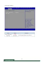
Страница 67: ...67 Control Legacy PXE Boot Feature Options Description Control Legacy PXE Boot from Disabled MGT LAN1 Control Legacy PXE Boot from which Lan...

Страница 68: ...68 Status LED Configuration Feature Options Description Status LED OFF GREEN RED Configures Status LED color...

Страница 69: ...utput 1 Output High Output Low Configure Digital I O Pin5 Digital I O Output 2 Output High Output Low Configure Digital I O Pin6 Digital I O Output 3 Output High Output Low Configure Digital I O Pin7...

Страница 70: ...70 Watch Dog Timer Configuration Feature Options Description Watch Dog Timer Enabled Disabled Enables or disables Watch Dog Timer function...

Страница 71: ...71 Serial Port Console Redirection Feature Options Description COM0 Console Redirection Enabled Disabled Enables or disables Console Redirection...

Страница 72: ...ars onto 1 or more bytes ANSI Extended ASCII char set Bits per second 9600 19200 38400 57600 115200 Selects serial port transmission speed The speed must be matched on the other side Long or noisy lin...

Страница 73: ...es VT UTF8 Combination Key Support for ANSI VT100 terminals Recorder Mode Disabled Enabled With this mode enabled only text will be sent This is to capture Terminal data Resolution 100x31 Disabled Ena...

Страница 74: ...esolution 80x24 80x25 On Legacy OS the Number of Rows and Columns supported redirection Redirection After POST Always Enable BootLoader When Bootloader is selected Legacy Console Redirection is disabl...

Страница 75: ...Enabled Enables or disables 64bit capable Devices to be Decoded in Above 4G Address Space Only if System Supports 64 bit PCI Decoding SR IOV Support Disabled Enabled If the system has SR IOV capable P...

Страница 76: ...XHCI Hand off Enabled Disabled This is a workaround for OSes without XHCI hand off support The XHCI ownership change should be claimed by XHCI driver USB Mass Storage Driver Support Enabled Disabled E...

Страница 77: ...p delay Auto Manual Maximum time the device will take before it properly reports itself to the Host Controller Auto uses default value for a Root port it is 100 ms for a Hub port the delay is taken fr...

Страница 78: ...rols the execution of UEFI and Legacy PXE OpROM Storage Do Not Launch UEFI Legacy Controls the execution of UEFI and Legacy Storage OpROM Video Do Not Launch UEFI Legacy Controls the execution of UEFI...

Страница 79: ...79 NVMe Configuration Network Stack Configuration...

Страница 80: ...P boot option will not be created Ipv6 PXE Support Disabled Enabled Enables Ipv6 PXE Boot Support If IPV6 is disabled PXE boot option will not be created Ipv6 HTTP Support Disabled Enabled Enables Ipv...

Страница 81: ...any of the items in the left frame of the screen Feature Options Description PCH Configuration None Displays and provides option to change the PCH Settings Server ME Configuration None Configure Serv...

Страница 82: ...s Configuration None PCI Express Configuration settings PCH SATA Configuration None SATA devices and settings Restore AC Power Loss Power ON Power Off Last State Select S0 S5 for ACPI state after a G3...

Страница 83: ...t Port Function Swapping Disabled Enabled Enable PCIe root port function swapping feature to dynamically assign function 0 to enabled root port Max Read Request Size MRRS 128B MRRS 256B MRRS 512B MRRS...

Страница 84: ...2 3 4 Disabled Enabled Enable or Disable SATA Port Hot Plug Disabled Enabled Designates this port as Hot Pluggable Configure as eSATA Disabled Enabled Configures port as External SATA eSATA Mechanica...

Страница 85: ...A Device Type Hard Disk Drive Solid State Drive Identify the SATA port is connected to Solid State Drive or Hard Disk Drive SATA Topology Unknown ISATA Direct Connect Flex M2 Identify the SATA Topolog...

Страница 86: ...86 Server ME Configuration...

Страница 87: ...87 Runtime Error Logging Feature Options Description System Errors Disabled Enabled Auto System Error Enable Disable setup options...

Страница 88: ...ays and provides option to change the Processor Settings Memory Configuration None Displays and provides option to change the Memory Settings IIO Configuration None Displays and provides option to cha...

Страница 89: ...89 Processor Configuration...

Страница 90: ...Enables Intel R TXT VMX Disabled Enabled Enables the Vanderpool Technology which takes effect after reboot Enable SMX Disabled Enabled Enables Safer Mode Extensions Hardware Prefetcher Disabled Enable...

Страница 91: ...91 Per Socket Configuration Feature Options Description CPU Socket0 Configuration None None...

Страница 92: ...ration Feature Options Description Core Disable Bitmap Hex 0 0 Enable all cores 3fff Disable all cores IOT Cfg Disabled Enabled Each bit enables IOT OCLA for a CBo Note IOT Enable will override RDT CA...

Страница 93: ...Options Description Memory Frequency Auto 800 1000 1066 1200 1333 1400 1600 1800 1866 2000 2133 2200 2400 2600 2666 2800 OvrClk 2933 OvrClk 3000 OvrClk 3200 OvrClk Maximum Memory Frequency Selections...

Страница 94: ...94 3400 OvrClk 3600 OvrClk 3733 OvrClk 3800 OvrClk 4000 OvrClk 4200 OvrClk 4266 OvrClk 4400 OvrClk Memory Topology None Displays memory topology with Dimm population information...

Страница 95: ...T d Configuration menu PCI E ASPM Support Global Disabled Per Port L1 Only This option enables disables the ASPM support for all downstream devices PCIe Extended Tag Enable Auto Disabled Enabled Auto...

Страница 96: ...ed to PCI Express Port 1A Socket 0 PcieBr1D02F0 None Settings related to PCI Express Port 1C Socket 0 PcieBr2D00F0 None Settings related to PCI Express Port 2A Socket 0 PcieBr2D02F0 None Settings rela...

Страница 97: ...ion Feature Options Description Sck0 IOAT Config None None Disable TPH No Yes TLP Processing Hint disable Prioritize TPH Disabled Enabled Prioritize TPH Relaxed Ordering Disabled Enabled Relaxed Order...

Страница 98: ...98 Intel VT for Directed I O VT d Feature Options Description Intel VT for Directed I O VT d Disabled Enabled Press Enter to bring up the Intel VT for Directed I O VT d Configuration menu...

Страница 99: ...Advanced Power Management Configuration Feature Options Description CPU P State Control None P State Control Configuration Sub Menu include Turbo XE and etc CPU C State Control None CPU C State setti...

Страница 100: ...mance Max Efficient Set by Intel Node Manager Select the performance state that the BIOS will set before OS hand off Energy Efficient Turbo Disabled Enabled Energy Efficient Turbo Disable MSR 0x1FC 19...

Страница 101: ...Autonomous Core C State Disabled Enabled Autonomous Core C State Control CPU C6 report Disabled Enabled Enables or disables CPU C6 ACPI C3 report to OS Enhanced Halt State C1E Disabled Enabled Core C...

Страница 102: ...s FRB 2 Timer Enabled Disabled Enables or disables FRB 2 timer POST timer FRB 2 Timer timeout 3 minutes 4 minutes 5 minutes 6 minutes Enter value between 3 to 6 min for FRB 2 Timer Expiration value FR...

Страница 103: ...Timer Policy Do Nothing Reset Power Down Power Cycle Configure how the system should respond if the OS Boot Watchdog Timer expires Not available if OS Boot Watchdog Timer is disabled System Event Log...

Страница 104: ...nts Disabled Enabled Enables or disables all features of System Event Logging during boot Erase SEL NO Yes On next reset Yes On every reset Choose options for erasing SEL When SEL is Full Do Nothing E...

Страница 105: ...s Description Configuration Address source Unspecified Static DynamicBmcDhcp Select to configure LAN channel parameters statically or dynamically by BIOS or BMC The unspecified option will not modify...

Страница 106: ...106 View System Event Log...

Страница 107: ...rame of the screen Feature Description Administrator Password If ONLY the Administrator s password is set it only limits access to Setup and is only asked for when entering Setup User Password If ONLY...

Страница 108: ...form reset Secure Boot Mode Standard Custom Secure Boot mode options Standard or Custom In Custom mode Secure Boot Policy variables can be configured by a physically present user without full authenti...

Страница 109: ...stem in Setup Mode Restore Factory keys None Force System to User Mode Configure NVRAM to contain OEM defined factory default Secure Boot keys Enroll Efi Image None Allows the image to run in Secure B...

Страница 110: ...hoose specifies boot device priority sequence from available Group device Feature Options Description Setup Prompt Timeout 5 The Number of seconds to wait for setup activation key 65535 means indefini...

Страница 111: ...to the system configuration The following window will appear after the Discard Changes and Exit option is selected Select Yes to Discard changes and Exit Setup Save Changes and Reset When Users have c...

Страница 112: ...4 Software Setup 112 Restore Defaults Restore default values for all setup options Select Yes to load Optimized defaults Note The items under Boot Override may not be the same as what is shown on your...

Страница 113: ...cess activity Link Activity Blinking Amber Link has been established and there is activity on this port Solid Amber Link has been established and there is no activity on this port Off No link is estab...

Страница 114: ...nd periodically restarts it Should the counter reach zero before the software restarts it the software is resumed to be malfunctioning and the processor s reset signal is asserted Thus the processor w...

Страница 115: ...overing procedures consume considerable time and effort but all you work might also be to no avail Eventually you are left with no choice but to ship the board back to the manufacturer Lanner understa...

Страница 116: ...features two physical BIOS ROMs soldered onto the motherboard carrying two separate BIOS images The Primary BIOS carries the image for system bootup the parameters of which can be overwritten while t...

Страница 117: ...OS used for this bootup I just found the system being booted from the Recovery BIOS what s next With the Recovery BIOS at work it can be asserted that the Primary BIOS is having such severe problem th...

Страница 118: ...e you start make sure you select the correct firmware version and go through the instructions for BIOS update in BIOS Engineering Spec and BIOS fix information in the Release Note thoroughly If you ca...

Страница 119: ...nsole port 1 Connect one end of the console cable to console port of the system and the other end to the serial port of the Remote Client System 2 Configure the following settings in the BIOS Setup me...

Страница 120: ...each pair up to a total of 4 pairs 3 Lanner Bypass Modules can bypass systems Ethernet ports on a host system during three instances Just on Just on is the brief moment when the internal power supply...

Страница 121: ...el download center at https downloadcenter intel com use the keyword search or the filter to access the driver s product page and then download the latest controller driver as well as the ReadMe docum...

Страница 122: ...customer s expense 5 The following conditions are excluded from this warranty Improper or inadequate maintenance by the customer Unauthorized modification misuse or reversed engineering of the produc...

Страница 123: ...Appendix G Terms and Conditions 123 RMA Service Request Form When requesting RMA service please fill out the following form Without this form enclosed your RMA cannot be processed...

Отзывы: