29
2.
Flip the PHM over to align
PIN1
of
the carrier with the
Cutout
of the
bolster plate.
3.
Flip the PHM over, with the package
land of the processor facing the
socket, carefully hold the PHM while
lowering it vertically to engage it to
the alignment pins of the bolster
plate.
4.
Make sure the PHM is sitting
horizontally on the bolster plate.
5.
Use a torque driver to tighten the
four nuts to 12 in-lbf into the bolster
plate following the sequence
indicated on the heat sink (#1
#2
#3
#4).
2
Cutout
Alignment Pin
Alignment Pin
3
4
5
Содержание NCA-5520
Страница 16: ...16...
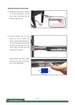
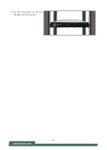
Страница 44: ...44 3 Fix the lock screws on the Ear Brackets to both front posts...
Страница 63: ...63 Super IO Configuration...
Страница 68: ...68 Status LED Configuration Feature Options Description Status LED OFF GREEN RED Configures Status LED color...
Страница 79: ...79 NVMe Configuration Network Stack Configuration...
Страница 86: ...86 Server ME Configuration...
Страница 89: ...89 Processor Configuration...
Страница 91: ...91 Per Socket Configuration Feature Options Description CPU Socket0 Configuration None None...
Страница 106: ...106 View System Event Log...


